
















In an era of smart factories, connected equipment, and increasing automation, it’s easy to assume that advances in technology have solved many of the challenges that once plagued wire harness manufacturing. Yet anyone responsible for crimp quality knows otherwise. Despite decades of improvements in machinery, sensors, and process controls, the terminal crimp remains one of the most critical and closely scrutinized operations in harness manufacturing.
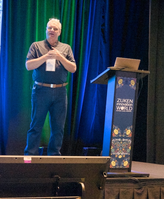
That reality was the focus of a well-attended technical session presented by Terry Curtis, President of WireProcess Specialties, during the 2026 Electrical Wire Processing Technology Expo (EWPTE) in Milwaukee. Drawing on more than 45 years of industry experience, Terry outlined what he calls the “Four Pillars of a Terminal Crimp,” a framework designed to help manufacturers build a process capable of producing reliable, repeatable, and verifiable electrical terminations.
While the presentation explored everything from crimp geometry and pull testing to Industry 4.0 networking, Terry repeatedly returned to a central theme: quality does not begin with the crimp itself. It begins with the systems and people that support it. “The success of a good terminal crimping program, or of any other area of your operation, depends on a solid foundation,” he stressed.
The Foundation Beneath Every Crimp
Before discussing crimp design or process monitoring, Terry challenged attendees to think about the broader structure supporting their manufacturing operations.
In his view, successful crimping programs rest on five foundational elements: management commitment, organization-wide training, effective production systems, robust quality systems, and continuous feedback through reporting and analytics.
That emphasis on management involvement is particularly important. Too often, crimp quality is viewed as something that belongs solely to operators, quality technicians, or manufacturing engineers. Terry argued that lasting success requires participation throughout the organization.
Management must understand the requirements of the crimping process and provide the resources needed to support it. Operators and technicians need role-specific training. Engineers must understand both the mechanical and electrical implications of crimp design. Everyone involved should be working from a common understanding of what constitutes a quality termination.
Terry also introduced another foundational concept that would reappear throughout the presentation: every crimp is the result of five interconnected elements working together.
Those elements are the wire, the terminal, the applicator, the crimp press, and the operator. “Any one of those elements drifting out of control can affect the overall quality of the finished termination,” he emphasized.
The statement sounds simple, but it carries significant implications. Manufacturers often focus on the terminal or the tooling while overlooking machine repeatability, operator technique, wire variation, or maintenance practices. Terry emphasized that process capability must extend across all five elements if manufacturers hope to achieve truly repeatable results.
The Science Behind the Crimp
From there, Terry moved into the first pillar: crimp design.
Although the physical act of crimping appears straightforward, a properly engineered crimp represents a carefully balanced interaction between wire, terminal, and tooling geometry. Terminals are designed for specific wire ranges, and the geometry of both the terminal and the applicator tooling plays a critical role in achieving the desired electrical and mechanical performance (figure 1).
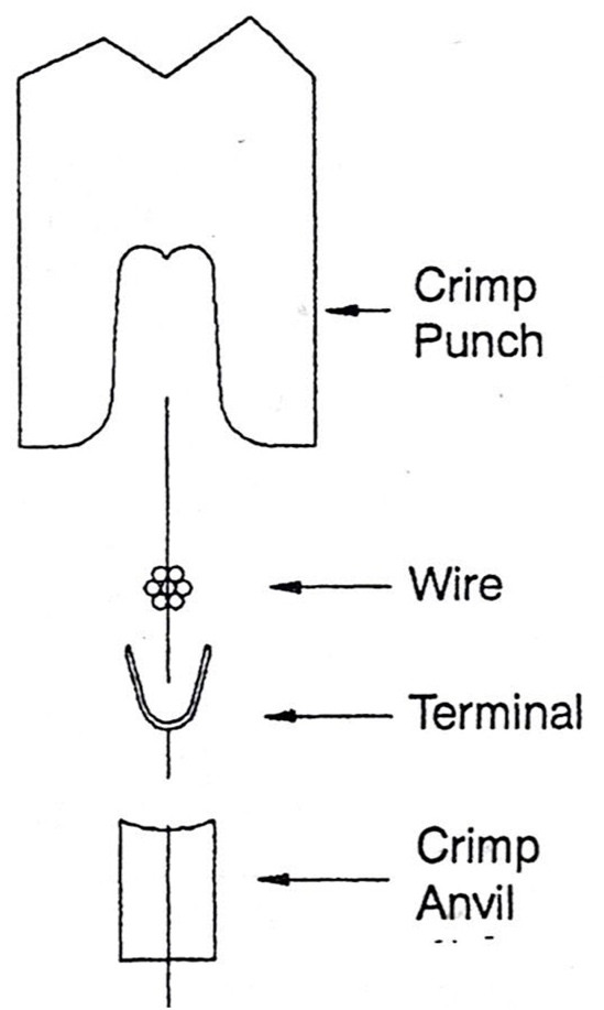
Figure 1. Wire terminal and tooling match.
Among the design features often overlooked are serrations, the small ridges stamped into the interior of the terminal barrel.
Many assemblers see serrations every day without giving them much thought. Terry explained that these features perform two important functions. First, they improve tensile strength by helping anchor the conductor strands within the crimp barrel. Second, they break through surface oxides on the conductor strands, reducing electrical resistance and improving conductivity, (figure 2[JT1] ).
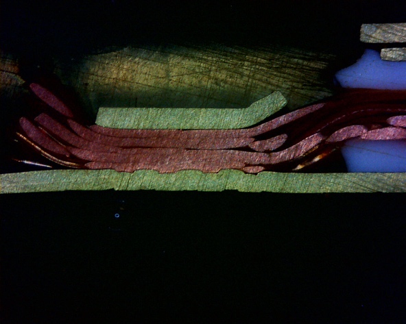
Figure 2. Serrations stamped into the interior of the terminal barrel.
Another important feature is coining, a subtle shaping operation incorporated into the terminal design that helps the crimp tooling begin forming the barrel more effectively as the crimp cycle starts, (figure 3).
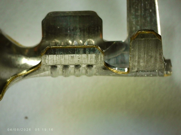
Figure 3. Coining in a terminal.
Understanding Conductor Compression
While these features contribute to crimp quality, Terry described conductor compression as the single most important characteristic of a successful crimp. “This is the meat and potatoes of the crimp process,” he told attendees.
The most revealing portion of the presentation focused on the relationship between conductor compression, electrical resistance, and pull force. Using a series of cross-sectional images and test results, Terry demonstrated how varying levels of compression affect crimp performance.
As conductor strands become increasingly compressed (figure 4), electrical resistance decreases. The reduction occurs because compression eliminates air gaps between strands and increases metal-to-metal contact within the crimp barrel. From an electrical standpoint, more compression generally means lower resistance (figure 5).
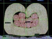


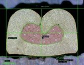
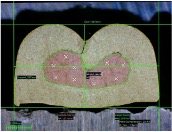
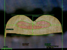
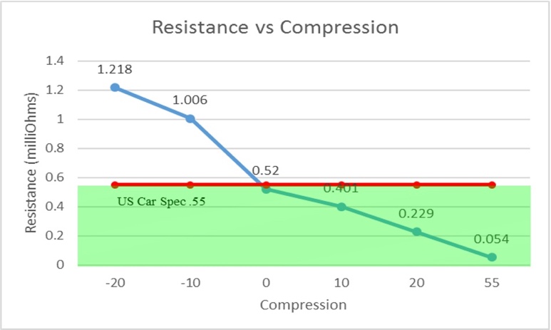
Figure 5. Relationship of resistance to crimp compression.
However, the relationship changes when mechanical performance is evaluated (figure 6).
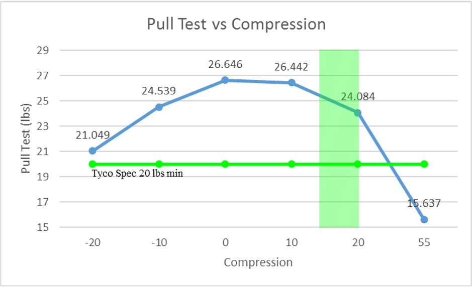
Figure 6. Relationship of pull force to crimp compression.
Pull-force testing reveals a different curve. Tensile strength increases as compression rises, reaches an optimum point, and then begins to decline. Excessive compression can damage conductor strands, reducing the crimp’s mechanical integrity even while electrical resistance continues to improve. This creates an engineering compromise.
If electrical resistance alone were the goal, manufacturers would simply continue increasing compression. If pull force were the only concern, a different compression level might be selected. The optimal crimp lies between those extremes.
Terry explained that this balance is one of the reasons terminal manufacturers specify conductor crimp heights and widths rather than relying solely on pull-force requirements.
Most properly designed terminals target a conductor compression range of approximately 15 to 20 percent. Within that window, manufacturers can achieve a desirable combination of low electrical resistance and strong mechanical performance.
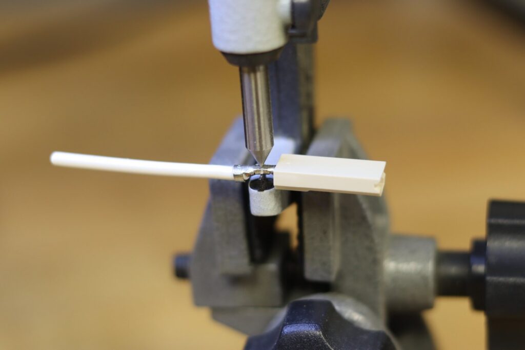
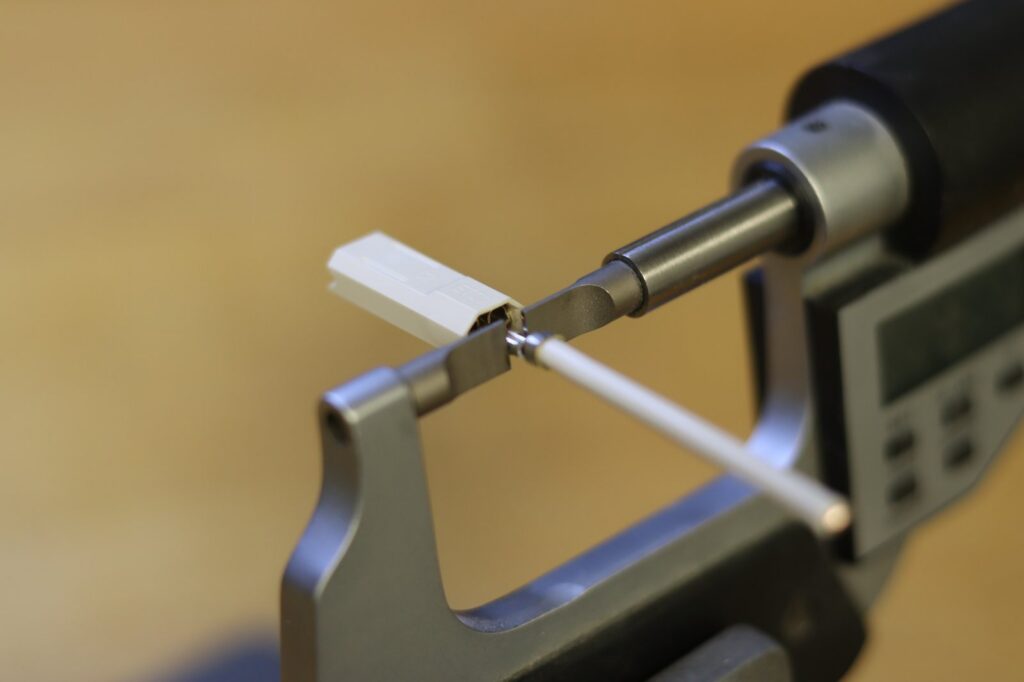
Understanding that relationship helps explain why crimp height remains one of the most important measurements in the crimping process. Conductor crimp height should be measured using point-blade micrometers. Width measurements and insulation crimp dimensions require appropriate blade-to-blade measuring tools. Consistent measurement practices are essential if manufacturers expect meaningful process control (figure 7a and 7b respectively).
Few quality tests are more widely recognized than pull-force testing. Yet Terry cautioned attendees against assigning too much significance to pull-force results alone.
Referencing requirements contained within USCAR-21, he pointed out that pull testing is intended to evaluate mechanical strength, not electrical performance.
That distinction is important because a crimp can pass pull-force requirements while still exhibiting undesirable electrical characteristics. “A lot of people think that just a pull test is good enough,” Terry said. “It’s not good enough.”
He also emphasized proper testing procedures, including the use of motorized pull testers whenever possible (figure 8).
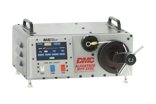
Figure 8. DMC’s MPT-250C motorized pull tester.
Automated testing eliminates operator-to-operator variation and improves result consistency. In automotive applications, motorized pull testers are often required by specification.
Visual Indicators Still Matter
While advanced monitoring technologies continue to evolve, Terry reminded attendees that many critical quality indicators remain visible to the naked eye.
Among the most important are insulation position, brush length, and bellmouth formation (figure 9a and 9b).
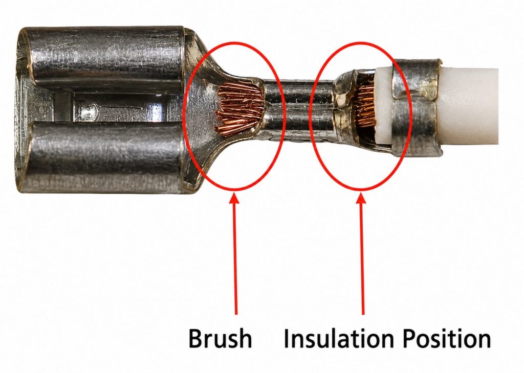
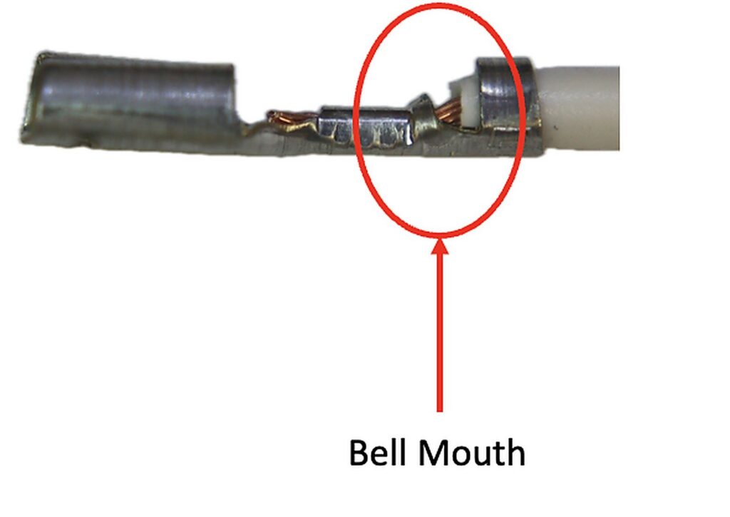
Figure 9a. Proper brush and insulation position. Figure 9b.Proper bell mouth depiction.
The insulation position window between the conductor crimp and insulation crimp provides immediate information about wire placement. If insulation is not visible where expected, assumptions must be made about wire positioning inside the terminal.
Likewise, the presence of conductor brush confirms that the stripped wire has fully entered the conductor crimp barrel. A missing brush may indicate incomplete conductor insertion.
Bellmouth formation, often misunderstood as a defect by inexperienced operators, is actually an intentional feature created during the crimping process. The flare helps protect conductor strands from damage as they enter and exit the crimp barrel.
These visual indicators provide valuable information, but Terry emphasized that they must be combined with proper measurement techniques.
Process Monitoring: Measuring What Happens Inside the Crimp
The third pillar focuses on process monitoring, specifically crimp force monitoring (CFM).
Crimp force monitoring has become one of the industry’s most effective tools for detecting defects during production. By measuring force throughout the entire crimp cycle, the system can identify variations that may not be visible during routine inspection.
Before a monitor can function effectively, however, a valid reference must be established.
Terry stressed that crimp force monitoring does not eliminate the need for proper setup and validation. Crimp height, width, pull testing, and other required quality checks must still be completed before production begins.
Once a valid crimp has been established, the monitor learns the characteristics of an acceptable force curve (figure 10). Each subsequent crimp is then compared against that reference.
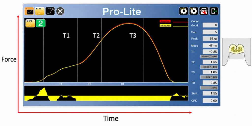
Figure 10. Acceptable crimp force curve.
As the tooling progresses through the crimp cycle, force data is collected and evaluated. Variations outside established tolerances can trigger alarms, stop presses, or initiate reject handling procedures.
The technology can detect a variety of defects, including missing strands, insulation trapped within the conductor crimp, and improper wire positioning (figures 11a,b and c respectively).
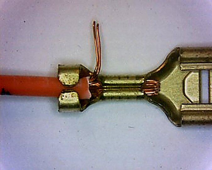
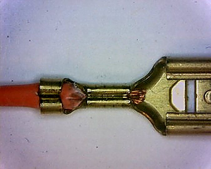
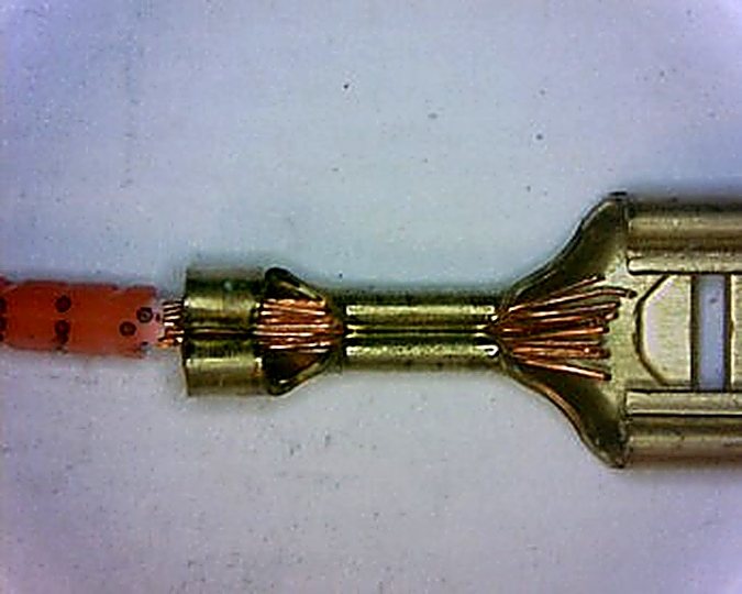
Yet Terry delivered one of the most memorable statements of the seminar when discussing crimp force monitoring. “Crimp Force Monitors expose, but do not solve your quality problems.”
Why Good Monitors Produce Alarms
Many manufacturers have experienced the frustration of nuisance alarms from crimp force monitors and Terry addressed that issue directly. Rather than blaming the monitor, he encouraged manufacturers to examine the underlying process.
Crimp force monitors are reference systems. They compare current production against a validated baseline. If the process itself is unstable, the monitor simply reveals that instability.
In many cases, excessive variation originates elsewhere. Tooling wear, inconsistent wire quality, machine repeatability issues, improper terminal selection, or poor conductor compression can all contribute to monitoring problems. “Don’t blame the monitor. Focus on your process,” Terry stressed.
The statement reflects a broader philosophy that appeared throughout the presentation. Process monitoring should not be viewed solely as an inspection tool. It should also serve as a process improvement tool.
Repeatability Drives Sensitivity
One of the more insightful portions of the presentation examined the relationship between process capability and monitoring sensitivity.
A highly repeatable process allows manufacturers to use tighter crimp force monitor tolerances. Tighter tolerances make the monitoring system more sensitive and improve its ability to detect smaller defects.
Conversely, unstable processes require wider monitoring windows to avoid constant alarms. As tolerances increase, the monitor becomes less capable of detecting subtle quality issues.
As covered earlier, a well-compressed crimp produces low electrical resistance, high pull force, and improved monitoring sensitivity. An under-compressed crimp exhibits higher resistance, lower pull force, and reduced defect detection capability.
But the implications extend far beyond quality inspection. Manufacturers seeking better monitoring performance often focus on monitor settings when the real opportunity lies in improving the repeatability of the underlying crimp process.
Cross Sections Tell the Truth
To better understand what is occurring inside a crimp, Terry advocated the use of cross-section analysis.
Cross sections reveal characteristics that cannot be observed externally. Properly formed crimp wings, full strand compaction, symmetry, absence of cracks, and correct conductor engagement all become visible when a termination is sectioned and examined.
Cross-section analysis also plays an important role in troubleshooting crimp force monitoring issues.
Problems that appear mysterious from the outside often become obvious once the internal structure of the crimp is exposed (figures 12a, b and c).
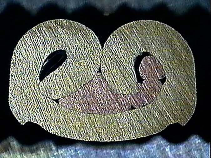
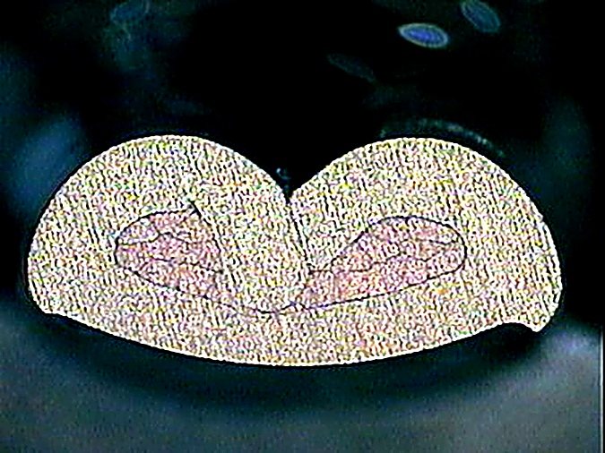
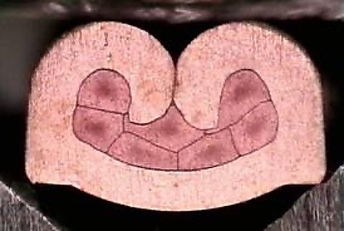
| Figure 12a. Crimp Legs Curling over and contacting the wall with (or without) strands encapsulated. | Figure 12b. Crimp Legs Crashing to the terminal floor. | Figure 12c. Crimp Wings Locked (No Gap).Full Strand Compaction (no round strands).Crimp Wings Symmetric.Crimp Wings Only Touch Conductor.Terminal Free of Cracks or Breaks. |
For manufacturers serious about process improvement, Terry described cross-section equipment as an invaluable diagnostic resource.
Looking Toward Industry 4.0
The final portion of the presentation focused on the growing role of digital connectivity within wire processing operations.
Industry 4.0 initiatives continue to expand throughout manufacturing, and Terry believes crimping operations can benefit significantly from integrated data collection and process management systems.
By connecting crimp presses, applicators, crimp force monitors, inspection equipment, maintenance records, and quality data into a common network, manufacturers gain improved visibility into process performance.
Such systems can support pre-production validation, in-process monitoring, maintenance tracking, traceability, record archiving, and reporting.
Yet Terry was careful to position Industry 4.0 as an enhancement rather than a replacement for the fundamentals discussed earlier.
Connected factories still depend on properly trained people, capable equipment, validated processes, and disciplined execution. Technology may provide greater visibility, but it cannot compensate for weak foundations.
The Real Lesson
While the presentation covered a wide range of technical topics, its central lesson was remarkably consistent. Reliable crimps are not produced by a single machine, measurement, or inspection tool. They result from a system of interconnected practices working together.
Strong management support coupled with effective training, good equipment and thorough process monitoring are crucial. Those elements form the foundation of a repeatable crimping process and provide the basis for meaningful continuous improvement.
For manufacturers searching for ways to improve quality, reduce variation, and increase confidence in their electrical terminations, Terry’s message was clear: master the fundamentals first. “The technology can only be as effective as the process supporting it,” Terry concluded.
For information on crimp validation, process improvement consulting, training programs, or technical assistance, contact Terry at: [email protected]. WireProcess.com.
Terry wished to acknowledge ETCO Inc. for supporting the seminar and providing many of the images and reference materials used in the presentation. Images courtesy of ETCO Inc.
—————
[JT1]need better serration photo