


Creative Use of Existing Instrumentation to Meet Exacting Requiremen
By Christopher E. Strangio, CAMI Research
Overview
Measurement of insulation resistance (IR) occurs by applying a voltage between two conductors and observing how much current flows through the insulation. Dividing the applied voltage by the flowing current using Ohm’s law produces a value of insulation resistance.
Typical PVC or Teflon electrical insulation work extremely well, and as a result, only a miniscule current can be detected, so little, in fact, that we refer to the current as “leakage current” and need to raise the voltage to hundreds or thousands of volts to achieve detectible current flow. This, in fact, motivated the development of high voltage testers many years ago.
Recently, testing cables and connectors at high voltages poses some new challenges. Advances in electronic packaging often involve fitting complex circuitry into ever-smaller spaces, particularly in airborne or spaceborne applications. Consequently, the interconnects between increasingly compact electronic modules must shrink as well. NanoD connectors have typical contact spacing of 0.025” (0.635mm), half the spacing of microD connectors which themselves reflect a similar reduction in contact spacing from the generation before microDs appeared on the market.
As connector design forces pins into smaller spaces, pin spacing shrinks, and high voltage testing for proper electrical isolation between pins pushes the applied test voltage down to avoid air breakdown. Requirements presented by our customers over the last few years now require an IR of 10 GΩ at 100 Vdc, and this, in turn, demands a current measurement sensitivity of 10 nA or better.
Here we describe how we combined two existing test instruments to achieve the exacting measurement, and (in Part II) the results and precautions.
The Method
My company’s CableEye® HVX-21 multi-channel high voltage cable test system offers a leakage current sensitivity limit of 200 nA which we can reduce to 100 nA for special applications using a sample-averaging method we developed. However, we still remain unable to reach the 10 nA sensitivity required for new applications.
Rather than re-engineer the programmable high voltage power supply in our tester to meet the new requirement, we use an existing source measure unit (SMU) — a single-channel high-voltage test instrument, Keithley 2400-series SourceMeter™ SMU, which has the needed sensitivity, and provides a remote-control capability allowing us to integrate it with our existing control software. The successful result met our objective quickly and efficiently and offers increased-sensitivity IR measurements at a much lower test voltage than had previously been possible.
Under normal operation, our HVX tester serves as a data-acquisition peripheral to a standard Microsoft Windows™ PC running our test software which issues control commands to the tester and reads responses from it as the measurements are completed. Test results appear on a video monitor for immediate review and diagnostics, and these results may be printed, if desired, to fully document the test. Referring to Figure 1, the tester receives commands through a USB channel to first perform a low-voltage continuity and resistance test on the attached wiring, also referred to as Unit Under Test (UUT).
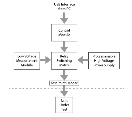
Figure 1
If the wiring matches the model cable and the connection resistances comply with the set limit, we disengage the low voltage module seen in the diagram through the relay matrix and drive a high voltage signal onto a distribution bus. Relays switch the high voltage stimulus signal onto the test points to which the UUT is attached. The system then sequentially applies high voltage to individual wires in the cable through the relay matrix while collecting leakage results from each wire tested.
Figure 2 illustrates a high voltage distribution bus and five typical relays. When a relay is energized, it connects the bus to a test point that drives a signal into the UUT. For a two-ended connection, two relays energize, one at each end of the wire. All relays that are not part of this connection remain de-energized and connected to the return path (ground bus). The electric field between the wire receiving the high voltage and all other points in the wiring presently at 0 V provides the opportunity for current to flow through any vulnerable areas in the insulation. Ideally, no current flow will be detectable.
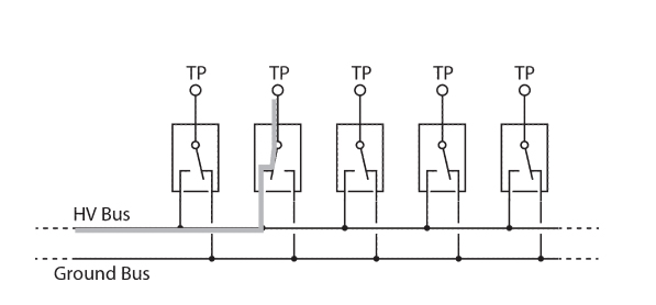
Figure 2
Figure 3 shows how an external instrument, in this case the SMU, replaces our internal high voltage generator. The SMU provides a high voltage stimulus needed to force current through insulation in the wire and has enough sensitivity to make the nanoampere current measurements we need.
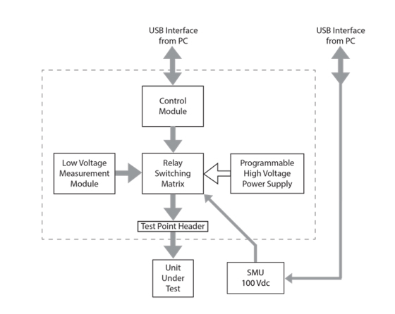
Figure 3
The system basically works the same way by first making a low voltage continuity test to confirm that the UUT is wired correctly and has acceptable connection resistance limits. It then engages the external SMU to apply 100 Vdc to the wiring network and measures the leakage from each wire. A second USB channel controlling the meter issues commands to ramp the voltage up, holds it for the specified dwell time, and returns a current leakage measurement to our PC control software.
We describe our results and precautions in Part II (appearing in next issue).