


THE ROLE OF THE BLADE IN A CALIBRATED WIRE PROCESS
By Ruben Lozano, B.I.E.
Picture yourself in the middle of a busy freeway. You’re traveling at night, at a high rate of speed, and SUDDENLY, your vehicle just stops dead. Everything just turns off!
Churning out low quality, unreliable wire circuits or defective, complex harnesses is certainly not the expectation of a wire harness manufacturer. Any wire harness producer worth their salt relies on first rate, efficient processes. One of the principal contributors of efficiency and quality in any process is a calibrated piece of equipment. Within the scope of a wire processing machine, there are three major process blocks: pre-process, process and post-process. Pre-and post-processes, like their names implies, are ancillary and supplemental procedures performed prior or after the main process. The actual process entails measuring a section of the bulk wire to length, cutting apart and stripping the ends of the wire and attaching connectors and/or other elements to those ends.
Since we are talking here about building electrical wire harnesses to be installed in vehicles, appliances, etc., then we can surmise that connectivity between the end points of each wire in the harness to its intended target is paramount. Thus, length accuracy in combination with proper electrical connections is an absolute must. These two key elements are contained within the main process of the machines and give us a clue on the mechanisms in the equipment that require calibration. In assessing these elements, we must analyze the feed traction mechanism, the cutting and stripping head and transport arms, and also the crimp presses and dies.
Calibration is understood essentially as the comparison of a result against a standard within a known and accepted value. As modern wire processing equipment has technologically evolved from its early years to present times, so has its calibration. Not only have the calibration standards evolved, so has the ability of the user to calibrate the equipment on-site. Early electro-mechanical machines were cam-and-lever based and were calibrated at the factory. They were difficult to re-calibrate in the field, especially as metal components became worn. Today’s machines are built with advanced quasi-robotic precise mechanisms based on light weight metals and other advanced materials. These work in combination with servo-motor based, computer controlled actions which not only reduce wear, but also allow software-based, user accessible calibration and re-calibration.
So, if we focus on the wire cutting and stripping procedure within the main process sequence, what should the role of the blades be in the calibration procedure?
Most users understand and recognize the role and importance of the terminal crimping tools as well as how to monitor and interpret the crimped terminal parameters after the process action. But not everyone fully understands or appreciates the contribution that a well-designed and manufactured blade has downstream in the success of the final crimping procedure. Maybe is the familiarity that we all have in using cutting blades in our daily life (knifes, scissors, etc.) which prevents us in recognizing that the blade is as much as a precision tool as a crimping die is.
I would venture to say that the best way to appreciate the role of the blade in the process is to consider it as an extension, or better yet, a recurrently replaceable part of the cutter head mechanism. As such, it should intrinsically have dimensional and geometric parameters in line with the design and functionality of the mechanism itself.
Modern Servo-motor driven cutter heads take advantage of the extreme accuracy of movement made possible by the controlled rotation obtained by the closed-loop system between the servo-motor and the angular location feedback provided by the encoder. This system enables the cutter head motion to provide a displacement motion as precise as 0.001 linear millimeters. The tachometer system allows the regulation of rotating speeds. These capabilities in combination empower the user to fine tune the equipment for optimal performance. As you can see from the illustration on Figure 1, the blade holder unit is precisely aligned in all three axes and in order to maintain the cutter head’s design functionality, any blade that is mounted on it should hold tolerance in all three axes as well.
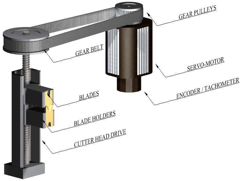
Figure 1. Servo-driven cutterhead components
To better understand this, let’s consider an example of how a cutter head, as well as a capture and transfer swing arm and clamp, in a modern piece of equipment would be calibrated by a user in the field:
(Procedure examples for model Cr.01 courtesy of ARTOS Engineering Co.)
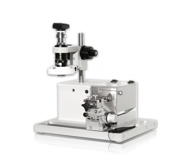
The machine’s cutting action is performed via a servo-driven cutter head mechanism which controls the opening/closing sequence. The servo-drive movement is in turn regulated by an on-board encoder reading which translates (via software), into the relative linear vertical position of the cutter head, namely where in the “Y” axis the blade holder is located at any given point. At the same time, other servo-drives and encoder combos determine where the transfer swing arm and capture clamps are in space (Fig 2).
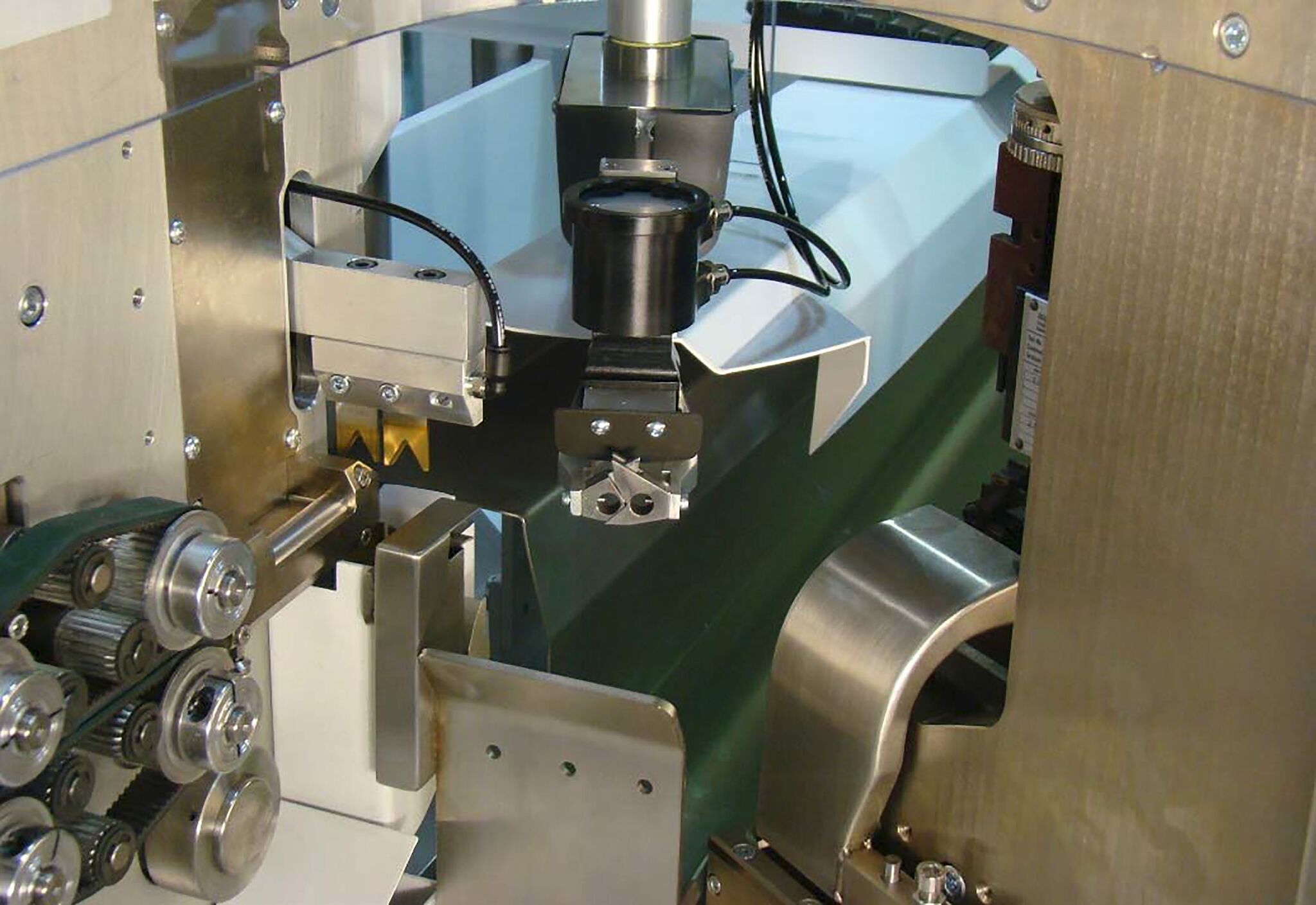
Figure 2. View of machine’s servo cutterhead and swing arm.
Determining the relative position in space of the blade holder, the swing arm and the wire capture clamp is the calibration’s fundamental basis. All we need now to complete the calibration, is to provide the mechanisms reference or “standard” point in space (Fig 3).
![]()
Figure 3. View of master setup fixture installed in blade-holder area prior to zero-point calibration
Figure 4 indicates the first reference point with the cutterhead in the open position. This is the maximum open position and allows the wire to be placed and positioned without any interference by the blades. This position can be fine-tuned to optimize the cycle time.
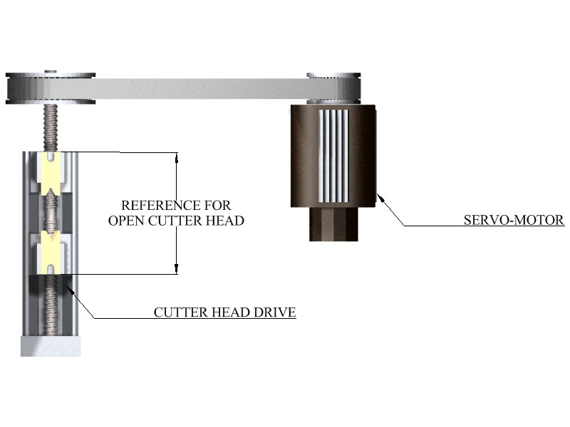
Figure 4. Servo head open.
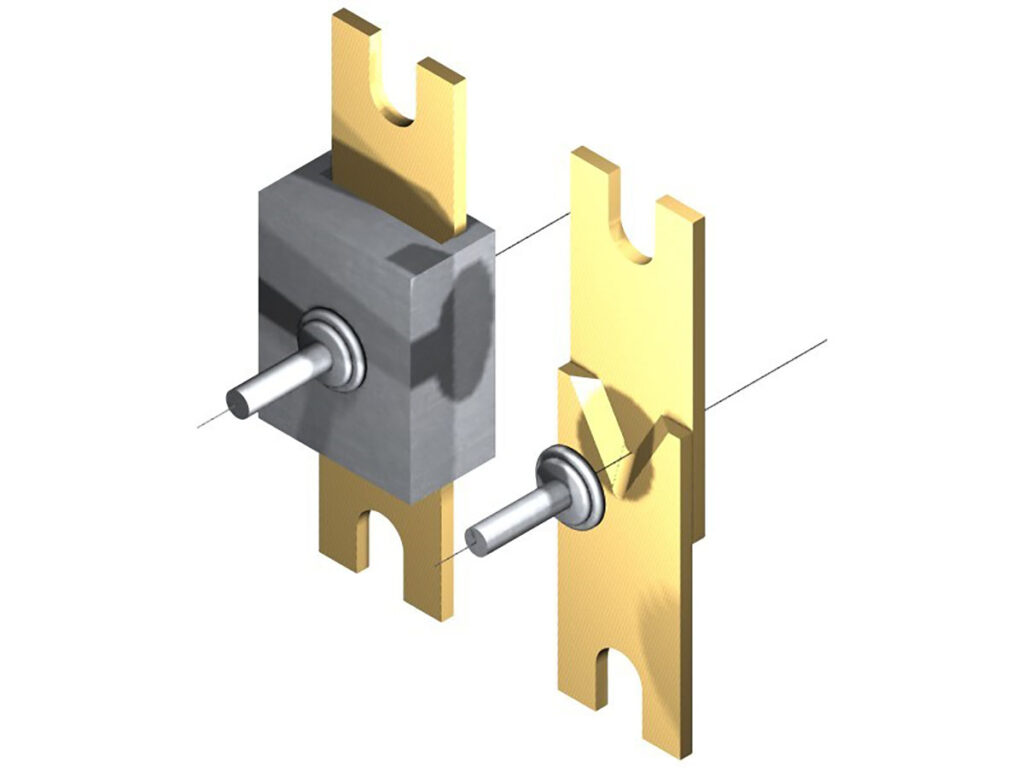
The second reference point with the cutterhead closed shown in Figure 5. This is also referred to as the zero-point, and it’s the point where the strip blades edge vertexes just begin to bypass each other.
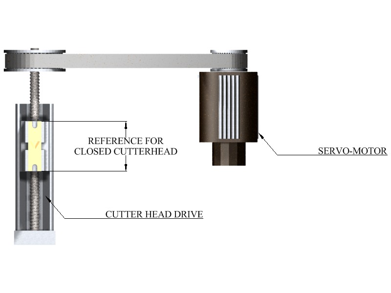
Figure 5. Servo head closed.
In the case of the ARTOS machine in the example, the cutter head reference point (or zero point) is where the bypassing blades have closed unto each other, and the vertexes of the blades are aligned in the same axes (blade edges at the vertex are just about to bypass each other). The swing arm position’s reference point (zero point) is determined by an aligned position with a predetermined closeness to the blade assembly. These two reference points are attainable by the use of ARTOS’s master calibration reference fixture that comes with the equipment. Finally, the swing arm’s rotational position is determined by its alignment to the crimp tool chamber as mounted on the crimp die onto the press. This position is variable, since different tooling and die styles and geometries don’t necessarily hold a constant position. Therefore, the operator must have the ability of reset this reference point as you substitute tooling and/or crimp dies (Fig 6 and Fig 7).

Figure 6. Point zero reference calibration for cutterhead gauge adjustments.
![]()
Figure 7. Calibrating the swing arms position vs. the crimp chamber.
Going back to the cutter head, the zero-point closure position becomes the standard reference point. The operator can then program any wire size (within the parameters of the equipment) at any time after the machine has been calibrated. Calibration itself should not be confused with setup. Re-calibration is performed only after machine repairs or replacement of worn parts. Once you calibrate the machine, then you’re done for an extended period.
As you can tell, the cutter head’s zero-point calibration is set by the relative position on the by-pass of the blade. This, in turn, is calibrated not visually by looking at the point where blade’s vertexes begin to bypass each other. Rather it is by the machine’s master calibration fixture dimension itself. This procedure assumes that the blade sets mounted are dimensioned exactly to the cutter head’s dimensional specifications. If not, the calibration setting would be invalidated by a faulty blade. This would be akin to expecting your car to roll smoothly while installing one oversized tire after an alignment was performed (Fig 8 and Fig 9)

Figure 8. Depiction of a blade set which is not manufactured to calibration tolerance, the blade’s relative opening to point zero calibration does not match the programmed gauge in the operator’s setup screen menu.

Figure 9. Showing a blade manufactured following the OEM’s calibration parameters, notice how it opens to the exact dimension to strip the wire without damage to the core. The blade’s physical opening matches the operator’s gauge selection on his/her setup screen.
This brings up a question we get all the time from wire processing blade users: Can you re-sharpen the blades? The short answer is no, because sharpening the edges modifies the relative position where the blade vertexes by-pass and thus, negates the machine’s calibration point. Subsequently the operator setup program is also invalidated.
In a wire processing blade, the dimension that turns it into an extension of the cutter head’s zero-point calibration is what is generally known as the “shut height.” The specific geometry is shown in Figure 10.
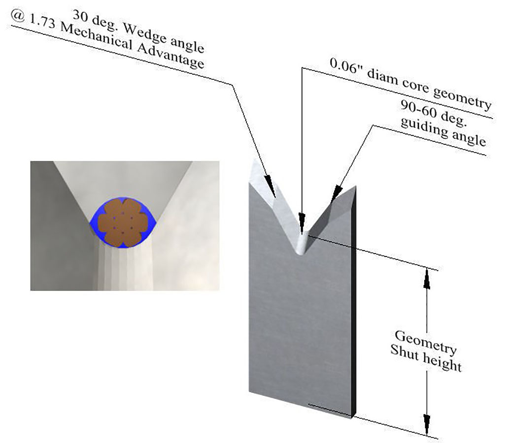
Figure 10. Examples of key dimensions for wire processing blades.
Since the blade’s edge is subject to wear and replacement, all the subsequent replacement blades should consistently hold this critical dimension. This way you are guaranteed that your calibration will always hold true and your process quality is maintained.
To illustrate the impact of the accuracy of new servo-driven, software controlled technology, the tolerance for this key dimension on blades has become five times tighter than the ones used by much older equipment.
Blades require as much precision as a crimp tool in their manufacture because not only are they an extension of the cutter head (and its accurate servo-driven mechanism) but they also guarantee that a calibrated process is taking place after each blade replacement. Lakes precision serves the globe with these precise, high quality OEM compatible tools.
Most of the major global wire harness houses have used our products for almost three decades and are still going strong. If you would like some clarification on any of these points, please feel free to contact me at [email protected]. And if you are looking for high-quality blade replacements, please consider Lakes precision. For USA, Europe, Canada, Asia: 715-546-3070. For the US southwest, Latin America and Vietnam region: 915-856-6606, 915-856-6607. Email inquiries can be made at [email protected].
Ruben Lozano is Vice President of Sales – Americas for Lakes Precision.