


In the previous two articles in this series, (Sept/Oct and Nov/Dec 2021) we compared automated to manual electrical testing and then examined how automated cable/harness testers make measurements. During those discussions, basic continuity, isolation, and high voltage testing were considered. In this article we’ll expand that range slightly by looking at 4-wire Kelvin testing, a capability possessed by many automated testers.
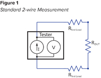
When we looked at a continuity test last time, we saw that the tester performs this resistance measurement by applying a known current through the circuit, measuring the voltage drop and then calculating the resistance using Ohm’s law. That formula states R=V/I where “R” is the resistance in ohms (Ω), “V” is the voltage in volts, and “I” is the current in amps. Continuity resistance measurements are typically performed using a standard 2-wire measurement configuration, which connects one test point to each side of the measurement. As seen in Figure 1, the voltmeter measures the voltage drop across the entire circuit including the resistance of the two test leads in addition to the resistance of the Device Under Test (DUT), which is the value of interest.
In a Kelvin (4-wire) measurement two test points are connected to each side of the measurement. One point acts as the “force” that supplies the current and the second as the “sense” which is used to perform the voltage measurement. The place at which the force and sense paths meet is called a Kevin point. The key benefit is that the measurement only includes the resistance between the Kelvin points (Figure 2).

In addition to providing the capability to eliminate the resistance of the test leads, the Kelvin measurement method typically provides a lower measurement range. It’s not uncommon for automated testers to provide a low limit of .1 Ω (100 mΩ) for 2-wire resistance measurements, but a low limit of .001 Ω (1 mΩ), or even lower, for 4-wire measurements.
When considering test fixturing, Kelvin testing obviously requires access to more test points. Additionally, assembling test fixtures using two pairs of connections for each Kelvin measurement introduces challenges. As Kelvin measurements include only the resistance between the Kelvin points, the force and sense paths should meet as close to the desired measurement as possible. A practical solution is to make this connection in the test fixture’s product mating connectors (Figure 3).
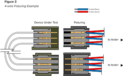
In this configuration the connection resistance of the connector contacts is included in the measurement in addition to the DUT resistance, but it’s often the best practical solution.
It’s also important to remember that automated testers allow the user to mix standard 2-wire measurements and 4-wire measurements in the same test. Therefore, 4-wire measurements are most often used only when necessary, which brings us to the subject of applications and when to use the Kelvin measurement method.
Sometimes this decision is made by the requirements of a test specification that calls for a resistance threshold below the test equipment’s 2-wire measurement range. However, it can also be the case that while the measurement is technically within the range of a 2-wire measurement, such a test can’t be practically implemented.
When faced with difficult test criteria it’s best to do some quick math to calculate the lowest practical acceptance threshold using a 2-wire measurement. If the calculation produces a value above the specification criteria, the Kelvin measurement method should be considered.
Briefly, the formula looks like this:
- Calculated highest resistance of an acceptable DUT
- Accuracy tolerance of the tester
- Fixturing resistance
- Lowest practical resistance threshold for DUT test
The calculated resistance of the DUT should be based on the highest acceptable resistance. Measuring a single sample will NOT provide a suitable substitute. Variables to include in the calculation:
- The resistance of the wire.Use the longest length allowed by the drawing tolerance and allow for any extra wire required in the connectors. If a wire specification isn’t readily available, consult a wire resistance chart or do an internet search for a wire resistance calculator to find the resistance for the appropriate wire gauge over a given unit of measure.
- There are differences in the resistance of solid and stranded wire and between stranded wire with different numbers of strands for a given gauge.Therefore, it’s best to use the resistance value specified by the wire manufacturer.
- Twisted pair wire has a higher resistance per unit of measure because the actual wire is longer than the overall measured length due to the twists.Typically, twisted pair wire has between 0.5% and 3% higher resistance that wires without twists.
- Most wire resistance charts are based on 20 degrees C (68 F).The wire resistance increases by approximately 4% for every 10 degree C increase in temperature (2.2% for every 10 F increase in temperature).
- Add the contact resistance of the connectors using the high-side of the manufacturer’s specified tolerance ranged.Depending on the characteristics of the connectors, the contact resistance will also increase with wear over time.
Next, the measurement accuracy of the tester must be included in the calculation using the high-side of the tester’s tolerance for the measurement range.
Finally, the resistance added by the test fixture should be considered. The same calculation process used for the DUT can be used again, however, as the fixturing is typically a fixed set, the actual resistance can be measured instead, if it’s possible to do so accurately. Be sure to include the contact resistance for the connectors and again, keep in mind that the contact resistance will increase with wear over time. However, as we’ve seen, this is the point at which Kelvin measurements can be extremely helpful as it can remove the resistance of test fixture from the equation. If using the Kelvin method, it’s only necessary to include the resistance in the test fixtures that exists between the Kelvin point and the DUT. For example, in the setup shown above in Figure 3, the contact resistance of the connectors is included in the measurement.
One real-world example that is often encountered is a very low resistance requirement from connector to connector through a shield. Frequently, the shield is terminated to the connector body and also wired through a connector contact to assure a good connection to the mating hardware. However, the test specification may require that a very low resistance measurement be made through the connector bodies to ensure good connections. In all cases, the key point to remember is that the 4-wire measurement is made from the point where the source and sense points meet (the Kelvin point).
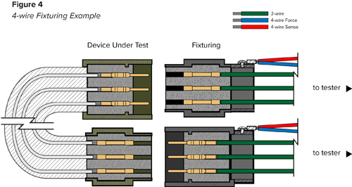
Depending on the characteristics of the connector, the Kelvin point can be made on the test fixture’s product mating connector body to simplify the testing process (Figure 4). Using this setup, the measurement would include the connection resistance of the two connector shells. This may be acceptable if that connection is expected to be very low resistance.
Another option would be to connect the Kelvin force to the test fixture’s product mating connector and the sense to the DUT connector body using an alligator clip or other temporary connection method. Both the force and the sense could also be connected together on the DUT connector using a similar temporary connection. Either option is only acceptable if the plating on the DUT connector body is conductive or if there is conductive hardware on the connector that can be used as a connection point.
In this example, as well as in other applications, once the Kelvin measurement method is understood, the best option can be selected depending on the test requirements and the circumstances. In a broader sense, it’s beneficial to know that Kelvin testing is an available tool and to recognize its benefits and the circumstances in which it can be most useful.