


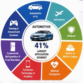


Since the 1970s, little has changed in automotive wiring. Manufacturers have added more wire and connectors, but everything still ties to legacy 12-volt systems. Thus, the architecture has remained basically the same. That is until the advent of HEVs and EVs. We have all heard the forecasts and read the OEM press releases about the coming electric fleets. And electrification doesn’t end there. Startups are testing and marketing electric buses, trucks, aircraft, lawnmowers…you name it and there is an electric version.
That’s really changing the landscape for cable assembly suppliers. A greater understanding needs to be gained about the intricacies of working with large diameter cable. To learn more, we scheduled a zoom call with Martin Rosten, Global Sales and Field Service Director at TE Connectivity based in Bensheim, Germany. To say Martin is an expert on the subject would be an understatement. He’s not only studied it, he’s done it.
Following was our Q & A session with Martin.
WHN: Let’s start by defining a large diameter cable.
Martin: We usually define large diameter wire as anything over 10 mm² (6 AWG). The wire size is actually a function of the current needed in the vehicle. Hybrids go up to 150 amps and require about 30 mm² wires. Complete battery electric vehicles have a much higher current requirement – up to 300 amps. There, we are already seeing sizes of 60 mm² to 90 mm². Even up to 120 mm² cables will likely be common in the future.
WHN: What is the typical construction?
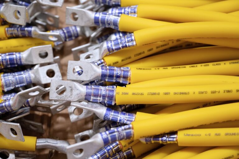
Martin: The high voltage cables themselves are very different from low voltage wires. They are comprised of multiple layers (Figure 1). Typically, you have an inner conductor with an inner insulation. Then you have an electric screen which is usually a tin-plated copper braid and, most often, a foil over top of that. This is to prevent the very high currents being carried in these high-voltage cables from interfering with the data connectivity or other systems present in the vehicle. And then finally, the cable has an outer jacket which is usually an orange silicone. Orange is the standard color to differentiate high voltage circuits in vehicles.

Figure 1. Components of a typical shielded high-voltage cable.
WHN: How are large diameter cables different as it comes off the reel?
Martin: The first thing that you will notice with high-voltage cables is what we call “footballing”. Because these cables are extremely large and heavy, and fed off fairly large spools, you get this footballing effect (Figure 2) which is basically where the wire end becomes slightly oval in shape. So, the first thing you have to do when you’re preparing the wire for a high-voltage cable is to make it perfectly round again. *

Figure 1. Example of “Footballing” in a 120 mm² cable
WHN: How is stripping these cables different?
Martin: You have more or less four separate processes that you need to carry out to get the wire ready for crimping. First is removing the outer jacket. The secret here lies in cutting deep enough so that you don’t risk tearing the insulation, but not so deep as to damage some strands in the copper braid underneath. That can cause a very unpleasant short circuit in the high-voltage system.
Once you get rid of the outer jacket, you need to remove the shield. First comes the foil which is basically a metal coated plastic tape. That has to be done very cleanly because you can’t have any of that inside the connection area between the ferrule and the braid. Once you remove the foil, you need to cut the copper braid itself. This must also be done very cleanly. Also, the braid has to be flared so that you can crimp the ferrule over it before you crimp the terminal to the inner conductor.
Finally, you have to strip the inner jacket. Like the outer jacket, you have to be very careful that you cut deep enough so you’re not tearing the insulation, but not too deep to risk nicking the inner conductor, which could cause issues to the electrical characteristics once you’ve completed the crimp.
WHN: What are the crimp challenges with large cables?
Martin: Obviously the main difference is the force needed to crimp wires of this size. With low-voltage wire, you’re typically crimping at less than 3000 lbs. With high voltage cables, you’ll be crimping around about 10,000 lbs. for midsize wire (upwards of 6 gauge) and then you can be as high as 40,000 pounds for the larger cables like the 90 and 120 mm². I would say most high-voltage terminations at the moment are in the 10,000 and 20,000 lb. range in terms of crimp force.
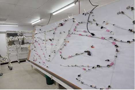
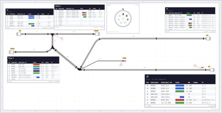
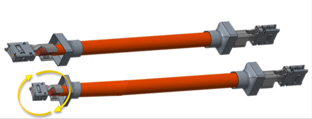
The next difference compared to small wire sizes is what we call “clocking”. It’s very important to know exactly where the center line of a conductor is because, if you can imagine, it’s almost impossible to twist a high-voltage cable. For long leads, you have some give in the cable. But for shorter leads and asymmetric terminals, the terminals will need to be installed in the proper orientation compared to the terminal on the other end of the cable (Figure 3) & this is what we mean by “clocking” the conductor.
Figure 3. Example of “clocking.”
The third difference to look for with crimping high-voltage cables is extrusion. Extrusion happens when you crimp any wire size, but obviously the larger the conductor cross-section, the more significant effect. Just to give you an idea, a 70 mm² wire will extrude about 5 mm. So, it’s very important to take that into consideration when you are calculating exactly where the wire needs to be inserted prior to crimping. Again, this is more important for shorter cable assembly lengths.
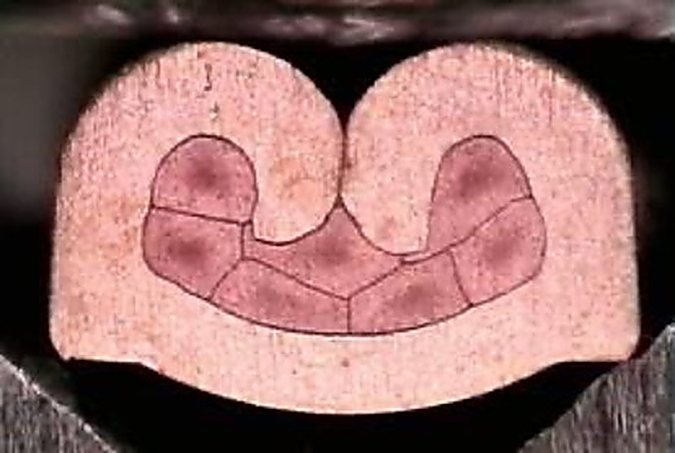
The last issue I want to talk about with respect to crimping, is cracking. Cracking can occur when crimping very large size wire terminals. It’s particularly unpleasant because you usually can’t see it with the naked eye. The only way you can detect it with a cross section analysis, so you really want to avoid any risk of cracking.
Usually cracking happens for three reasons. First, it can happen if you over crimp the wire. That’s why it’s very important to follow the manufacturer’s recommendation for the crimp height. It can also happen if you are using inappropriate wire sizes. So, for example, if you’re using a wire which is too big for the terminal, you might get cracking. Finally, and most important, it can also occur if the crimp cycle is too fast. We have found that in crimping very large wire sizes, that speed is very important. That’s why TE, and other high-quality crimp presses, have adjustable speeds. Typically, the larger the wire size the slower the optimal crimp speed.
In rounding out the discussion of crimping, I should mention that ultrasonic welding is also being used quite a bit in high-voltage terminal connections. With ultrasonic welding, you avoid some of the challenges that I’ve just described with crimping. However, ultrasonic welding is a costly capital outlay. It’s also slower than crimping and it requires very high levels of energy. It’s definitely an option, but I would say the majority of high-voltage connections today are still made with the crimping process.
The last area where we have a significant differential compared to small wires is the handling. That’s quite simply due to the sheer weight of these high-voltage cables. Just to give you an idea, A 50 mm² cable that is only 2 m long weighs 1.5 kg. That really does limit how you manipulate these cables in the assembly area. You can’t form large bundles of wire as you might with small wire sizes. It would just be inconceivable to move such a weighty assembly. This also limits the extent to which high-voltage cable production can be automated.
There are some automated cable processing systems already on the market. Komax and Schleuniger, among others, are producing fully automatic systems, but I would say that the majority of production of high-voltage cables assemblies is still carried out using semi-automatic equipment. This is simply due to the fact that production volumes are relatively low for the time being. That, coupled with what I was just saying about the difficulty of handling such heavy cable assemblies, means that semi-automatic processing is also more easily integrated into an existing harness assembly plant.
We do see full automation coming, that’s for sure. Most forecasts show the volumes increasing very significantly after 2030 which will make the necessary investments to automate much more cost effective.
WHN: What advice would you give high voltage assemblies manufacture in order to be successful?
Martin: I guess I would start with the most obvious and that is you need to use high-quality tooling. It’s very important that the tooling is easy to set up, and that it’s going to be stable to allow consistent crimping quality.
Another point to mention with high-quality tooling is you will typically get much more durable and longer lasting wear parts. As you can imagine wear parts for these very large crimp applicators are quite expensive. The longer they last, the better the economies in the production cycle.
Also, the applicator has to be set up correctly. You have to use a skilled operator who understands how the applicator needs to be adjusted. It’s very important this operator follows the manufacturer’s recommendations for the correct crimp height to avoid the issue of cracking.
And then, as a follow on to high-quality tooling and correct set up, we do absolutely recommend you use a good CQM (crimp quality monitor). Given the safety critical nature of high-voltage assemblies within the vehicle, as well as the cost of that assembly, it’s very important to ensure that you are crimping correctly and consistently. As a complement to the CQM system, we at TE are also able to offer a vision control which is integrated into the press (Figure 4). It scans the terminal, the wire and the applicator. It basically ensures that everything is in the correct position before the crimp is carried out. It will also allow you to visually inspect the crimp terminal once the crimp cycle has been completed, verifying that both the terminal and all the other components are in the correct angle and in the proper position.

Figure 4. TE’s Integrated Vision System.
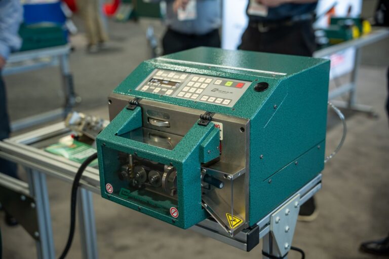
Next, we would strongly recommend harness manufacturers equip themselves with a high-quality cable prep machine. It doesn’t really make sense to economize there because you’re going to end up with a high scrap rate. High-voltage cables and terminals are extremely expensive compared to low-voltage. You will definitely benefit by reducing the scrap level to an absolute minimum.
And then the last comment that I would like to make here is that a high-voltage cable assembly is made up of multiple different components, many more so than a low-voltage connector and cable. So, you really need to think about the order that you’re going to assemble these parts and ensure the assembly area is well prepared and has the right tooling for each individual operation. And if you do that, you’ll certainly find that you will be able to make significant improvements in the speed of production of these cable harnesses.
* Martin mentioned it would be quite complex to explain exactly how TE does that in this article. He did mention that the patented technology TE has developed for their HV-CP cable prep machines ensures that the cables are returned to a round shape before the final incision is made. We will explore further in a future article.
Many thanks to Martin Rosten, and also to Michael DiLeva, Director of Communications – Technical Transport Solutions, for facilitating the interview. Special thanks to Deanna Mccoy, External Communications Consultant at TE who always comes through in connecting us with awesome experts at TE!