


As a starting point, the failure rate of connectors is estimated to be 1-2 orders of magnitude greater than general aircraft wiring. There are many reasons for this including:
- Exposed conductors
- Stiff connectors shells placing stress on wiring
- Mating/demating of the connectors
- Bent pins
- FOD
- The difficulty of ensuring every single wire terminated in the connector is done properly (i.e., correct crimping/soldering, correct wire insulation strip length, inserted into the correct cavity, etc.)
Because of the greater likelihood of connector failures, it is important to assess the failure modes and effects within connectors. Furthermore, with the growing need to support higher voltage power systems on aircraft, a new set of challenges is emerging. While not entirely new, these are new challenges for the aerospace industry.
PIN SPACING
Electrical arcing inside of connectors mainly comes down to pin spacing. At sea level, 1000 volts can jump a 1-millimeter gap, 10,000 volts can jump about a 1-centimeter gap, and so forth (these are not exact numbers, but it is a good starting point for many assessments). These breakdown voltages assume normal atmospheric conditions without local atmosphere ionization.
Looking at an example connector with 2.4 millimeters of separation between the pins, a voltage equal to or greater than 2400 volts would be needed to jump the gap. Keep in mind that this is referring to the peak voltage, not the RMS voltage. To achieve a safe separation distance for a 2500VRMS system would require a spacing greater than 3.6 millimeters (the 2500VRMS system would have peak AC voltages of 3535V) plus some separation distance for margin to handle transients; for the example here an additional 50% margin will be added creating a pin-to-pin separation/clearance distance of 5.4mm.
This rule of pin spacing is not valid when applied to higher altitudes. With the reduced pressure at altitude, the voltage breakdown reduces between 20 – 40% (assuming aircraft operation between 30 – 40kft). This would then push the required clearance distance between the two pins in the example up from 5.4mm to 9.0mm. This estimation does not consider the impacts of temperature and ionization; if there is an elevated temperature or the potential for local ionization, the separation/clearance distance would need to increase.
Of course, this addresses the dielectric breakdown of air between the pins and not surface creepage (to be discussed in a future Lectromec article, but tests like the Comparative Tracking Index testing can provide a starting point).
CONTAMINATION AND FOD
Connector failure is more than air breakdown, and most connectors are designed to prevent direct paths between conductive surfaces. If there is any contamination inside the connector, the surface resistance may be reduced and can lead to noise on data lines, cross-circuit activation, arcing, and shorting; also depending on the contaminant, the contact resistance may increase. This resistance increase may be the result of corrosion (fluid plus voltage potential and heat are a great combination to accelerate corrosion) or with the decrease of clean contact area between the mated contacts. increasing attenuation in data circuits and increasing heat generation in powered circuits. It can be considered odd that the contamination can potentially increase and decrease the resistance within a connector, but different contaminants will yield dissimilar results.
ARCING WITHIN A CONNECTOR
If an electrical arcing event occurs within the connector, it is unlikely that any of the systems within the connector will remain undamaged; this is true even if circuits are protected with high-speed circuit protection devices. As such, the arcing event failure mode should be considered a complete loss of the connector. When considering this from a perspective of FAA wiring system safety regulation, 25.1709, this aligns with the physical failure branch which requires an applicant to consider that an entire wire harness is destroyed due to an arcing event, regardless of fault probability.
PHYSICAL DAMAGE
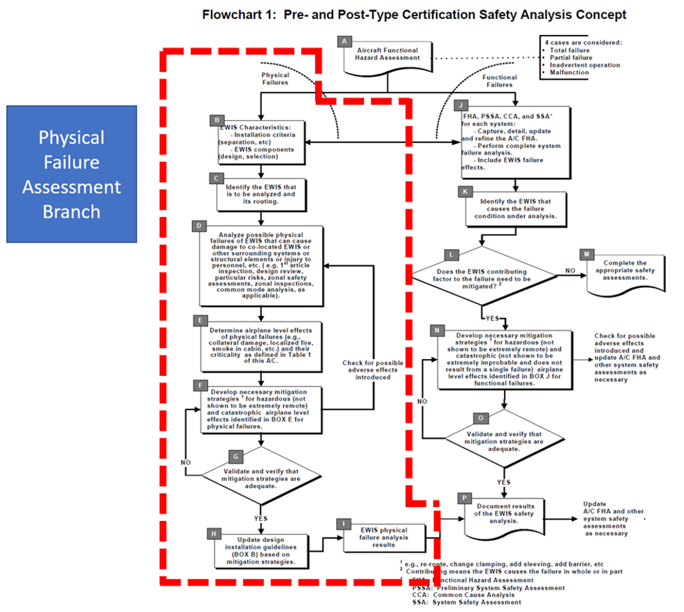
An important part of the functional hazard assessment is identifying possible physical failures and ensuring adequate mitigation procedures to prevent hazardous conditions.
Connectors can experience physical damage due to mishandling, improper insertion or removal, excessive force, or accidental impacts. Physical damage may include bent pins, broken housings, or cracked components, which can lead to connection problems or complete failure. When considering HV connectors, it now becomes a new set of component assessments necessary to determine what physical damage level will be acceptable for continued service. While some degradation of connector inserts might have been acceptable for low voltage connectors, the acceptable degradation of HV connectors will need to be validated through testing and direct assessments.
PART SELECTION
When selecting connectors for high-voltage applications, there are several recommendations that should be considered:
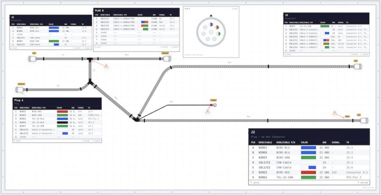
1. Consider what systems are routed in the connector. Where practical, redundant systems should not be routed in a single connector much less a connector where the failure mode can be significant.
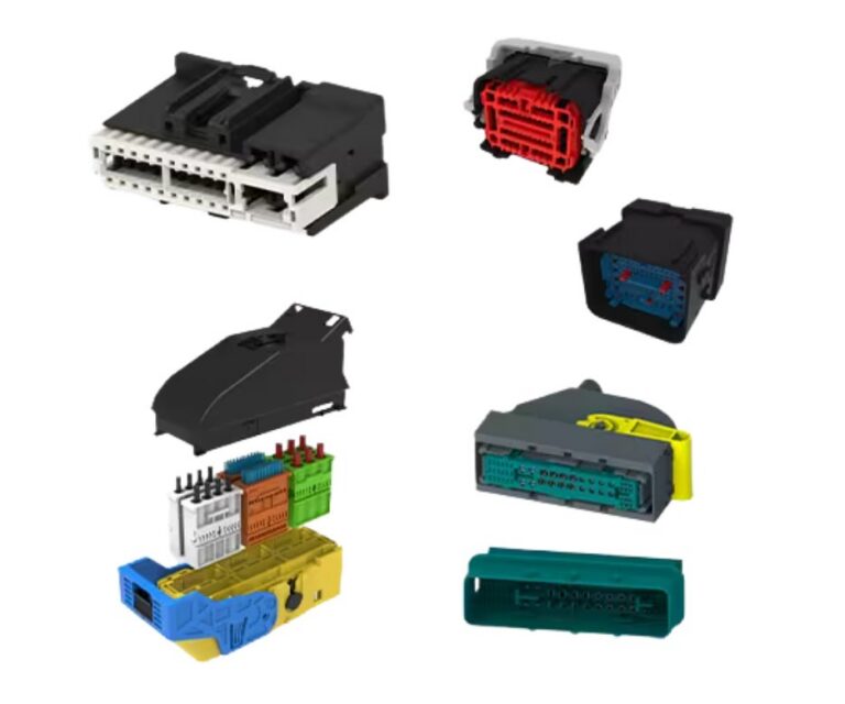
2. Connector designs that include shorter pins that demate before the main power pins. This design is seen on external power cables and on USB devices. The idea is that the shorter pins disengage before the main power pins and are part of the main power shutoff circuit (for example, the short pins are connected to a contactor that opens once the connector starts to demate). This is a generally accepted design for high power connectors, but this design option does carry a weight penalty to account for the shorter pins, larger connector shell, and additional wiring necessary to detect the connector opening.
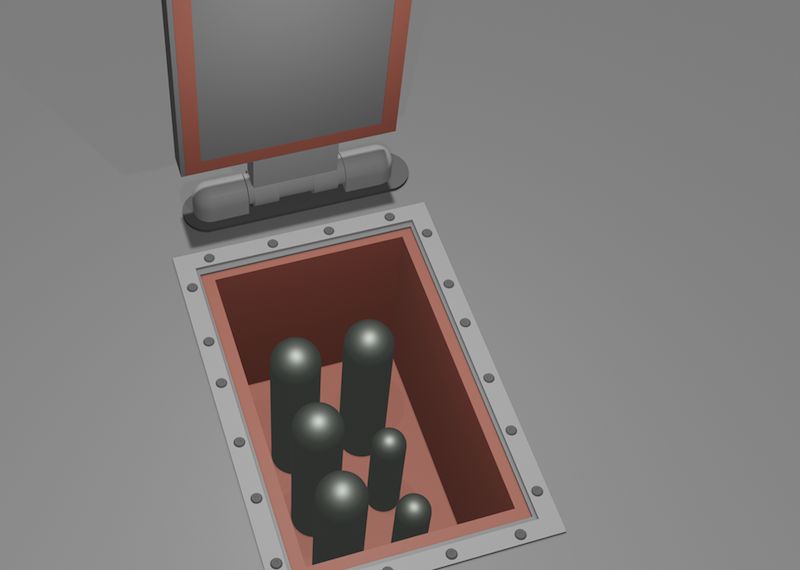
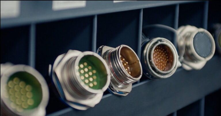
An example of a connector with pins of different lengths to control a shutoff circuit, the short pins are connected to a contactor that opens once the connector starts to demate.
3. Consider the Altitude. When testing was done on several types of standard MIL-STD-38999 connectors at reduced pressures, it was observed that partial discharge values dropped to just over 300 volts for several different connector configurations. Obviously, those connector types are not viable for high voltage high altitude applications. Additional tests should be considered when selecting connectors for high voltage applications which include:
- Ultimate dielectric breakdown.
- Partial discharge inception and extinction voltages.
- Accelerated aging of the connector using the system voltage and waveform.
With connector testing, it can be difficult to isolate the degradation of the wiring from the degradation of the connector. As such, testing should be close to system configuration is possible to not just assess the connector but then also assess the manufactured part including termination, repeatability, and workmanship.
QUALIFICATION
The need for high-grade, high-voltage, aerospace connectors will be here to stay for a long time. How these connectors are validated for HV application without life-limiting the parts will take a fair bit of research and progressive field testing. By addressing and understanding the failure modes of connectors and how the service life will stress the components, long-term, reliable solutions are achievable.
For those looking for support with component and system level verification of wiring system components performance, contact Lectromec. Our knowledgeable engineers and ISO/IEC 17025:2017 accredited lab are here to help.
About Lectromec:
Lectromec has been a leader in wires and wire interconnect systems since 1984 and has provided expertise to the aerospace industry, both military and commercial. They help organizations worldwide improve the safety and readiness of their air fleet and reduce the costs associated with aircraft maintenance. www.lectromec.com.