


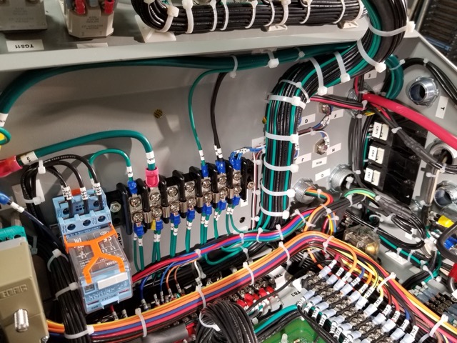


Heat Shrink Tubing is a commonly used component in a wide variety of wiring applications; its applications include electrical insulation (particularly at termination points where conductor may be exposed), abrasion resistance, insulation repair, wire management (bundling), etc.
For aerospace, the most common heat shrink tubing is made in accordance with AS23053. Here we review the background, an overview of the qualification tests, and deeper dive into the more interesting tests.
AS23053
A commonly used testing standard for Heat Shrink Tubing for aerospace applications is the SAE AS23053 (currently in Revision A, most recently revised in 2019). The testing standard is very broad and covers “various types and colors of electrical insulating sleeving that will shrink to a predetermined size upon the application of heat.” Specified properties and requirements for tubing of particular materials can be found in associated AS23053/XX specification standards.
The AS23053 standard covers the following classifications of inspection:
- Initial qualification inspection
- Retention of qualification inspection – every 36 months after the initial qualification date. The current retention status of AS23053 suppliers can be found under the “QPL-SIS” tab https://www.navair.navy.mil/qpl/
- Quality conformance inspections
This discussion will also briefly address the ASTM D2671 “Standard Test Methods for Heat-Shrinkable Tubing for Electrical use”, as it is frequently referenced and applied in the SAE AS23053.
In 2001, the US military standard for heat shrink tubing (MIL-DTL-23053E) after it, and many other standards, were taken on by the SAE. The MIL-DTL-23053 is now superseded by the SAE AS23053.
TESTS
As with any component intended for use on aircraft, heat shrink tubing test standards are rather extensive and aim to thoroughly verify the component’s quality. Not every test method will be addressed in this article, but some of the more interesting ones are highlighted.
RESTRICTED VS UNRESTRICTED SHRINKAGE
Two methods are employed for shrinking heat shrink tubing for testing: restricted shrinkage and unrestricted shrinkage. Both methods achieve a similar goal – to shrink the tubing prior to testing, their methodologies, however, differ critically.
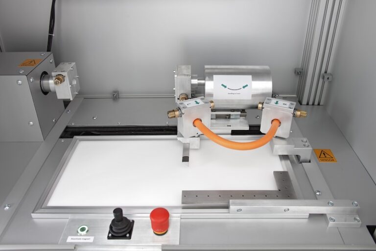
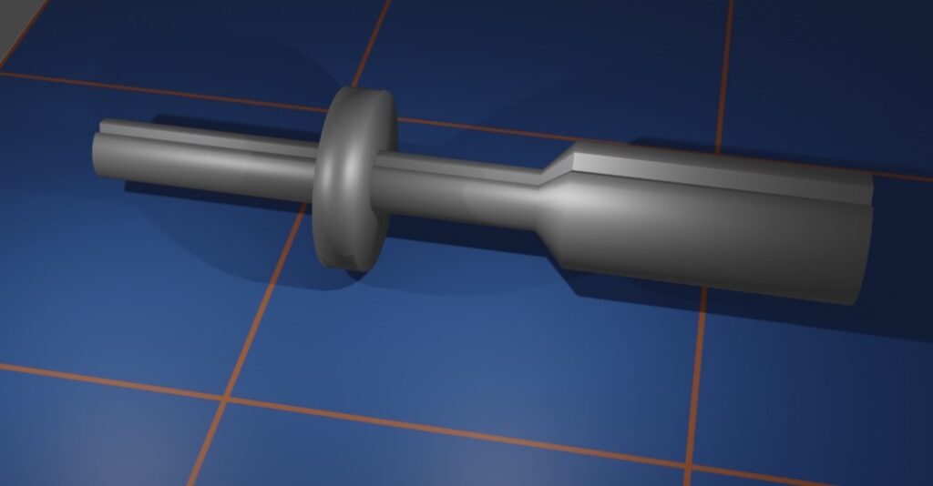
Restricted Shrinkage is performed on a conductive metallic mandrel with the intention of using the mandrel as a representative internal conductor for voltage withstand testing after the shrinkage (fig. 1). The shape of the mandrel is shown in the accompanying images.
Unrestricted shrinkage may be performed with the specimen resting on an oven tray or supported by a mandrel whose diameter matches that of the maximum acceptable sleeving inner diameter size.
Nearly all testing is performed on tubing after undergoing “Unrestricted Shrinkage”. This ensures that the data collected from testing accurately represent the capabilities of the tubing in application.
The following properties are tested after unrestricted shrinkage as part of the unrestricted shrinkage evaluation
- Color
- Color stability
- Clarity stability
- Specific gravity
- Dielectric constant
- Fungus resistance
- Tensile strength
- Ultimate Elongation
- Dielectric strength
- Volume resistivity
- Low temperature flexibility
- Corrosion
- Heat resistance
- Water absorption
- Flammability
- Fluid resistance
- Sealing efficiency
The following properties are tested after unrestricted shrinkage but are not implicitly part of the unrestricted shrinkage evaluation
- Dimensional measurements
- Cold impact
Very few tests are performed on the heat shrink tubing as it is provided by the supplier: dimensional measurements, heat shock, secant modulus, and restricted shrinkage.
FLUID RESISTANCE
Heat shrink tubing specimens are tested to evaluate their resistance to damage or degradation caused by commonly present aerospace fluids. The standard test fluids are as follows:
| Fluid | Conforming to |
| Hydraulic fluid, petroleum base | MIL-PRF-5606 |
| JP-8 | MIL-DTL-83133 |
| Lubricating oil | MIL-PRF-7808 |
| Lubricating oil | MIL-PRF-23699 |
| 5% NaCl | A-A-694 |
| Deicing Fluid | AMS 1424 |
Virgin specimens are exposed to one test fluid for 24 hours and then evaluated for tensile strength, ultimate elongation, and dielectric strength. Heat shrink materials must be capable of maintaining their properties after exposure to common aerospace fluids to ensure any level of confidence in the component.
HEAT SHOCK
Heat shock is one of the few heat shrink tests that is performed without any pre-shrinking procedure. Testing consists of a 4-hour oven exposure with the specimen hanging vertically inside the heat chamber/oven. Throughout the elevated temperature exposure, and after the exposure is completed, the specimen is visually monitored for any evidence of cracking, flowing, or dripping; observation of any of these defects is cause for test failure. In the case that the specimen does not show evidence of these defects, it is removed from the oven, returned to ambient conditions, and evaluated via a 360o bend test around an appropriately sized steel mandrel. A final visual examination is then performed to check for any specimen damage.
CONCLUSION
Heat shrink tubing is a very commonly used component in Electrical Wiring Integration Systems (EWIS). Just as with any other component of an aircraft wiring system, heat shrink tubing must withstand extensive severe testing before being approved for use. How these products will evolve with the next generation of aircraft wiring systems is uncertain. Areas that could use new heat shrink tubing products include higher temperature ratings as the maximum rated temperature of the existing heat shrink is about 200oC. Similar to other parts of the EWIS, heat shrink may need to evolve to address the needs of high voltage systems, but this remains to be seen.
If you’re looking for qualification testing for your heat shrink tubing product, or for guidance on which heat shrink material is right for your system. Contact Lectromec today! Our ISO 17025:2017 accredited lab is here to help.
Author
Laura Wishart
ENGINEER, LECTROMEC
Laura has been with Lectromec since 2019 and has been a key contributor to projects involving testing of EWIS/fuel system failure modes, the impact of poor installation practices on EWIS longevity, and wire/cable certification testing and training. Her knowledge and attention to detail ensure consistent delivery of accurate test results from Lectromec’s lab.