


Cable and Harness Testing: Checking the Quality of Connections
Overview:
Today, most companies manufacturing and/or integrating cables and wire harnesses, will test electrical integrity with programmable, automatic multiconductor testers – time-saving, productivity-boosting equipment that checks for and locates faults across all conductors of the Unit Under Test (UUT) without operator intervention.
Resistance measurement capability within a multiconductor cable tester is not simply for measuring the values of resistors.
As well as measuring any embedded resistors, the resistance-measuring feature of a cable tester is needed when measuring the quality of the connection and the quality of the non-connection. This test is recommended whether or not products have embedded resistors.
To check the quality of a connection, you must check for good intended connections as well as good intended non-connections (Fig. 2), and for that you need a tester that a) measures resistance, b) allows you to set up limits, also known as dual thresholds, and c) allows you to check for intermittent connections.
Without performing these checks, you run the risk of releasing or accepting faulty product. It is important to know and understand the parameters against which your cable or harness has been judged to have “passed”.
![]()
Figure 2: Good Connections and Non-Connections
What are “Dual Thresholds”?
Dual threshold set-up is required to check for connection quality (Fig. 3).
Without measuring resistance, the tester will tell you when your intended connection is connected (passing a simple continuity check), but not whether that connection is compromised by something that affects the total resistance of that connection perhaps, for example, because of poor soldering. In short, resistance measurement capability within a tester is not simply for measuring the values of resistors.
For most cables, you do not need to measure the actual resistance of each wire. Rather, you would like to confirm that the resistance of a good connection does not exceed a maximum limit, and that the isolation between unconnected wires does not fall below a minimum limit. We refer to these two limits as thresholds.
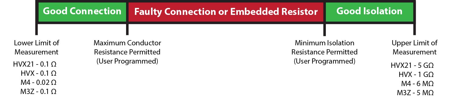
Figure 3: Dual Thresholds
CableEye measures embedded resistors automatically when the resistor value falls between the high and low thresholds. When you save a cable in the database, the resistance values associated with any embedded resistors are saved along with the tolerance, wire list, and other cable information. Thus, embedded resistors become one of the characteristics of the stored cable and must be present in a test cable to successfully match against the saved data.
For this example (Fig. 4), the Maximum Conductor Resistance Permitted has been user defined within the software as 0.5 Ω and the Minimum Isolation Resistance Permitted has been set to 1 MΩ. The cable measured contains a resistor between pins 5 and 5. The 2.70 kΩ resistor falls not only between the upper and lower limits of measurement shown on the drawing above (e.g. 0.02 Ω and 6 MΩ for the Model M4), but also between the user-programmed resistance limits, so it is displayed as an embedded resistor.
Conductors between SH, 1, 2, 3, 4, 6, 8 and 9 are all under 0.5 Ω, and are displayed as good quality connections. The connection between pins 7 and 7 is above 0.80 Ω, which is above the Maximum Conductor Resistance permitted. This line is highlighted as a fault, and the cable is failed.
You can easily experiment with your own tester if you have a selection of resistors and a test interface fixture with screw terminals. Connect the resistors to the test interface fixture and adjust the resistance thresholds to see how the tester displays the results.
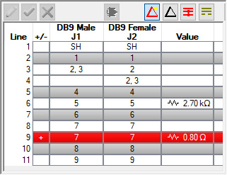
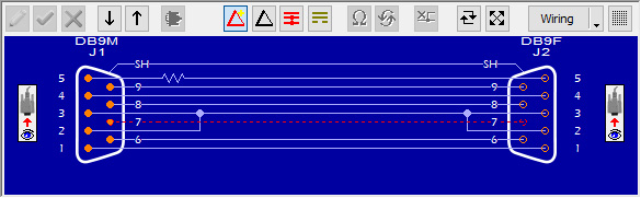
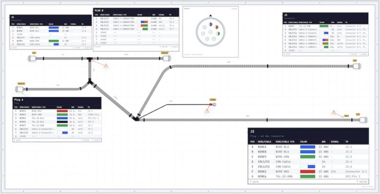
Figure 4: Example of Netlist (Top) and Wiring (Bottom) Results
What Constitutes an Acceptable Connection Resistance?
The Maximum Conductor Resistance Permitted sets the highest value of resistance acceptable for a “good” connection.
Wire connections in a cable that exceed your maximum resistance threshold will be flagged as defective. High-resistance connections like this may be caused by incomplete crimps, by insufficient mating between the knife-pin and wire conductor in IDC flat cables, or by cold solder joints in soldered connections. These marginal connections may then result in circuit misoperation, intermittent connections, or physical heating in the cable if enough current flows through that connection.
In a properly managed cable assembly shop, high resistance connections occur rarely. However, resistance testing is needed to ensure that absolutely no bad cables make their way into a customer’s product. This is especially important for product destined for mission-critical applications such as aerospace, military, and medical devices. For example, you may set CableEye HVX-series continuity and HiPot systems to check for an acceptable connection resistance of as little as a few milliohms (refer to Fig. 3 for other models). Such low resistance checking is often recommended for shells and shields.
The best test systems will allow you to optimize your test by letting you set different thresholds for different conductors in your cable or harness. For example, you may set the Maximum Conductor Resistance Permitted to a very small value only for the shells and shields, and other values for the other conductors.
If you set this value to less than 5 Ω, the measurement time may increase by a factor of two or more due to the increased sensitivity you are asking for, and you may pick up marginally higher resistance values that will have no effect on the function of the cable. Other than for shells and shields, use the smallest threshold of 0.5 Ω or less only when you test power cables or any cables that are expected to carry significant current (20 gauge or thicker wire).
What Constitutes a Short Circuit?
The Minimum Isolation Resistance Permitted sets the lowest value of isolation resistance acceptable for unconnected wires.
In addition to certifying that a wire connection passes a low resistance test, we must also ensure that internal short circuits do not exist. While this seems obvious, we need to define exactly what constitutes a short circuit.
To certain sensitive electronic devices, especially in medical applications, a “short circuit” may exist in a cable when as much as a 1 MΩ (or higher) resistance path appears between two pins.
In contrast, the high output drive capability of present-day CMOS digital circuits can easily maintain the logic ‘1’ minimum voltage across a short circuit of as small as several hundred ohms.
Ideally, we would like an infinite resistance between isolated conductors. As a practical matter, though, a lesser amount will be quite adequate for most applications. We recommend a minimum isolation threshold of 1 MΩ for general purposes, although you may set the isolation threshold to a higher value, depending on your tester model. Refer to Fig. 2 to determine the maximum value that you can set your isolation threshold to.
Note that the contact resistance of dry human skin is about 2 or 3 MΩ. To minimize the likelihood of false negatives during production testing, we recommend setting the isolation threshold above 1 MΩ only when you are testing cables that will be used in a high voltage or extremely low current application.
Why Check for Intermittent Connections?
We define an intermittent connection as a temporary but radical change in resistance between two points occurring unpredictably when motion or stress is applied or when a change in temperature causes expansion or contraction of an electrical contact.
Poorly mated pins, broken wires, and poor bonding, among other things, may cause intermittent connections. Checks for intermittent faults are performed after a successful, static continuity and resistance check.
An intermittent open circuit applies to a low resistance connection which, for a short period of time, becomes disconnected (high resistance). An intermittent short circuit applies to two normally unconnected conductors which, for a brief period of time, short together (low resistance).
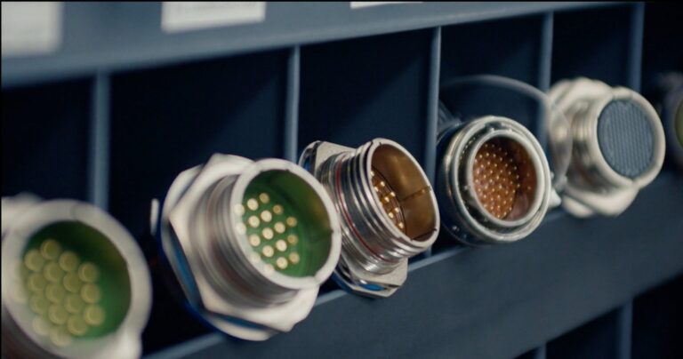
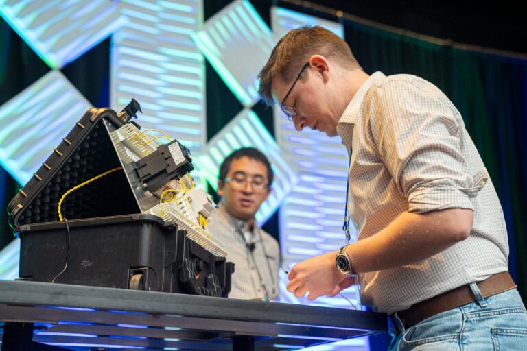
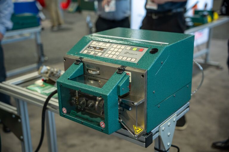
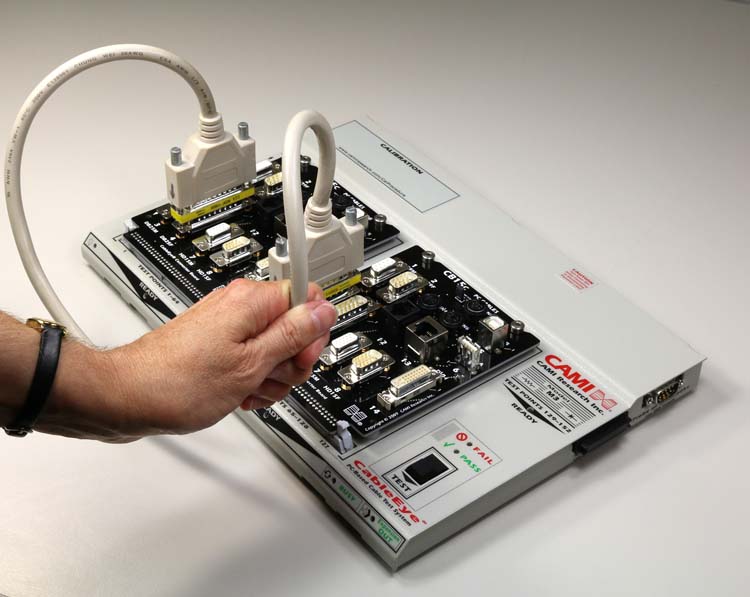
The intermittence test is dynamic: During the test, you flex the connectors and apply stress (including pull) to the cable (Fig. 1) while the tester sends a continuous stream of test pulses under fast cycle times. A full cycle comprises a complete sweep through all test points.
The CableEye software offers two methods for checking for intermittent connections; one detects continuity differences only (opens/shorts) and another detects and reports resistance variations. Furthermore, to report the resistance variations there are two options, 2-Wire or 4-Wire resistance measurements. The Continuity Only Test offers the fastest scan rate.
The test is properly performed when the sample rate is high enough to statistically capture enough random events to raise the confidence level in the test result to an acceptably high degree. Companies running stringent quality programs (such as Six Sigma) will be looking for the fastest cycle time possible. They need testers that deliver diagnostic information above a simple PASS/FAIL, so they can provide quantitative and qualitative data to their process-improvement feedback loop.
In advanced testers such as CableEye systems, when the test runs, a tone will sound if any faults are found, the error count will increment, and a wiring diagram will display all accumulated intermittent connections highlighted (Fig. 4). In this case, we see an intermittent short between pins 2 and 3 and an intermittent open between 1 and 1 were detected. With 19 full test cycles being completed every second, in 570 test cycles, 22 error events were detected.
It is clear that this is a faulty cable and this test has correctly identified it as such – in addition to identifying and locating the errors. If this dynamic test had not been performed, this cable would have been falsely determined to “PASS”: all tester indicators, labels, and reports would incorrectly show as “PASS”.
Note that with a slower test cycle frequency, fewer of these error events would have been detected. At a slow enough rate, despite running an intermittence test, none might be detected resulting in a false “PASS”. It is important to pay attention to the cycle rate setting.
Clearly, checking for faults in this way will be able to tell you exactly which, if any, wire has a break. Generally, the most likely location of a break is at the end of the wire i.e. at the connector. If a cable has been pulled (experienced tension), it is possible that a break might occur along the length. Cables for robotic applications might break along the length especially if the repetitive motion causes the cable to rub against a hard point or exceed the recommended radius of curvature.
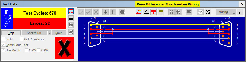
Figure 5: Real-time intermittence testing identifies a) the number of passes and errors, b) the type of error (color-coded), c) the location of the error.
Conclusion
It is a common misconception that measuring resistance is only required if the product has embedded resistors. We have shown the importance of checking the quality of connections and that this requires the ability to measure resistance, to set upper and lower limits, and to check for intermittent connections.
It is also a common mistake to assume that a cable is fault-free just because a tester PASS light lit up, or because you have an auto-generated printed report with a “PASS” title.
Be sure you understand the pass parameters against which the tester is making the determination.
Check that your test system is capable of measuring the quality of the connections, and that it has been set up to do so with the right values for your product and its application.
If you are subcontracting your harness and cable manufacturing, ask your supplier to confirm this information and, if necessary, to reset the pass criteria on their tester.
Our thanks to CAMI Research Inc. for this paper. If you would like to contact CAMI, you can do so at (978) 266 2655, or go to camiresearch.com.