


5 KV SHIELDED CABLES VS. NON-SHIELDED
by Anixter
Non-shielded 5 kV cables have been used for many years because
they are lower in cost, require less space, and have smaller and lower- cost terminations compared to shielded cables. However, cable users sometimes experience problems with non-shielded installations that can be solved by using shielded 5 kV cable.
SHIELDING ADVANTAGES
• Limits voltage stress on the insulation
• Dissipates insulation leakage current
• Removes capacitive charging current
• Carries ground-fault current to facilitate operation of ground-fault
protective devices
• Protects anyone who comes in contact with an energized cable
Shields in shielded cables reduce high-voltage stress and prevent corona from forming on the surface of the cable insulation, which can be caused by dirt and moisture accumulation. Corona discharge occurs when a charging current flows between the conductor and the ground through the ionization of surrounding atmosphere. Ozone will attack the conductor insulation and jacket and eventually result in insulation failure.1
To increase the safety and reliability of shielded cables, the shield should be grounded properly. Additionally, the cable needs to be terminated by applying stress-relief terminations, which greatly reduce the possibility of arcing.
STANDARDS
In Canada, 5 kV non-shielded TECK90 cables are manufactured per CSA C22.2 No. 131-17 with 90 mil insulation thickness for 6 AWG to 1000 kcmil sizes. However, 5 kV shielded HVTECK cables are made in accordance with CSA C68.10-14 and are available with two insulation thicknesses for 8 AWG to 1000 kcmil sizes: 100% (90 mils) and 133% (115 mils). 2
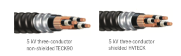
5 kV three-conductor 5 kV three-conductor non-shielded TECK90 shielded HVTECK
In the U.S., per table 1.1 in UL 1072 Edition 4, a shield is required
for voltage ratings greater than 2400 V. For 5 kV shielded armoured cables, they are made per UL 1072 and UL 1569 and available with two insulation thicknesses for 8 AWG to 1000 kcmil sizes: 100% (90 mils) and 133% (115 mils). 3
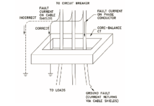
SHIELD ROUTING THROUGH ZERO SEQUENCE CT
In many installations, a zero sequence (core balance) current transformer (CT) is used for phase-to-ground fault detection on medium-voltage feeders. However, the shield or ground wire routing is often incorrect, which leads to inability of the CT to detect a phase-to-ground fault. Therefore, shield or ground wires need to pass back through CTs before being connected to ground. This practice ensures the magnetic field produced by outgoing and return current will not be canceled and allows the CT to detect a phase-to-ground fault.4
1 2017 National Electrical Code Handbook, Article 310
2 CSA C68.10-14, Table 8
3 UL 1072 Edition 4, Table 15.1
4 Some Lessons learned From Commissioning Substation and MV Switchgear Equipment, IEEE, PCIC-2000


