


Wire Harness Data Migration Success
By David Selliman
Here’s the deal-breaker regarding retiring CATIA V4 UNIX workstations. With the need to retire the UNIX workstations comes the need to convert CATIA V4 to CATIA V5 with wire harness data. Up to this point, no company on the market had a solution. Moreover, the need to automate the process is a must with the needed requirement to include all information within the data set to be workable parametric in CATIA V5.
This paper outlines migration strategies at Lockheed Martin (LMC) that address objectives, return on investment considerations, quality issues, and best practices.
Objective
Lockheed Martin Corporation (LMC) had a requirement on its high-profile production programs to convert multiple CATIA V4 electrical wire harness datasets to CATIA V5, using an automated process with consistent results. The scope of this project was primarily for electrical harness installation datasets and their associated harness assemblies of which may span or share relationships to multiple installations that are resident in CATIA V4. The 3D dataset needed to be validated against its original. LMC was seeking an automated solution that retained essential intelligence and associativity between the harness installations, harness assemblies, and unwrapped (flattened) harness authored in CATIA V4 during the conversion to CATIA V5. The end results were needed to retire the old UNIX workstations, in order to regain the ability to manage the wire harness in CATIA V5.
Background
The manual process for converting electrical harness data did not produce an output that was usable or desired. A substantial amount of post process cleanup was required, with inconsistent and invalidated results. The labor-intensive manual process failures after migration from CATIA V4 provided a good insight into the requirements needed for software development. The automated solutions would include:
Harness Installation Dataset – A LMC harness installation is a 3D representation of all the parts listed in the bill of materials that are necessary to complete the installation of the harness assembly in the specified location in the aircraft (Figure 1). These parts include the harness assembly, supports (clamps), and necessary attaching hardware (nuts, bolts, etc.). Also, the harness installation will contain reference geometry. The reference geometry includes items that are not part of harness installation’s bill of material but provided context for the installation. The reference geometry will consist of structural members such as bulkheads, stringers, skins, as well as tubing and equipment that may also be installed in the surrounding area. The structural members generally include a secondary support structure, like brackets to which the harness supports are attached. This 3D data is used to create a traditional 2D drawing depicting the harness installation. Note that a harness assembly called out in a single installation may be included in other harness installations and, in such a case, will have associations to multiple harness installation datasets.
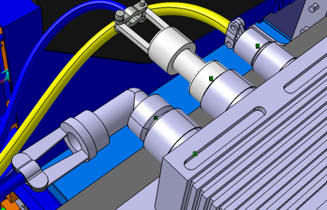
Figure 1 – 3D representation of all the parts listed in the bill of materials.
Harness Formboard Dataset
The harness formboard is a representation of the unfolded or unwrapped harness assembly lying on a 2D plane. The harness formboard data is more than a simple projection of the harness to a plane. The unfolded harness retains the actual trunk and branch lengths of the 3D harness assembly and correctly positions connectors, back shells, and other parts that make up the harness such that twisting of the harness is not required upon installation. A traditional 2D drawing (the Harness Assembly Drawing [HAD]) is a part of the Harness Formboard Dataset and depicts the unfolded harness assembly as it will be positioned on the gridded manufacturing formboard tool. The drawing includes part callouts and other necessary assembly fabrication information.
Harness Data Conversion – Requirements Definition
The CATIA V4 3D harness installation .model files shall be migrated to CATIA V5. The solution shall preserve the CATIA V5 associativity between the harness installations and their respective harness assemblies, flattened 3D harness, and formboard after the migration of the model. The result of the migration shall produce four CATIA V5 CATProducts:
- The 3D Harness Installation CATProduct
- 3D Harness Assembly CATProduct
- The Flattened 3D harness assembly CATProduct
- CATIA V5 CATDrawing of the Formboard.
The provided solution shall replace all the migrated CATIA V5 standard parts in the harness installations and harness assemblies with CATIA V5 parts from LMC’s provided electrical standard parts catalog, and re-create the links between all branchables and their associated electrical devices.
The provided solution shall also re-establish links between electrical devices (e.g., Branchables, Supports, Connectors, Backshells, Shells and any other electrical devices) in the 3D harness installation, 3D harness assembly CATProduct and Flattened 3D harness assembly CATProduct.
The provided solution shall re-establish the associativity between the 3D harness installation CATProduct and 3D harness assembly CATProduct and the V5 CATDrawing formboard. The solution provider shall ensure the CATIA V4 identifiers are applied to the reference designator, instance names for all CATIA V5 converted 3D harness assemblies, and 3D flattened harness assemblies. Finally, the solution provider shall re-establish links between electrical devices (e.g., Blanchable, Supports, Connectors, Back-shells, Shells and any other electrical devices).
Solution:
When CoreTechnologie received the request for proposal, the internal discussion was simple. LMC had already been a customer under CoreTechnologie’s interoperability solution for a decade; therefore, a choice to not submit a proposed solution was not a choice at all. More importantly, not having the expertise in wire harness conversion and the unknown to answer without phase one of the development plan was a known fear from both LMC and CoreTechnologie. Along with the statement of work, LMC provided a sample dataset in CATIA V4. After two weeks of discovery, the proposal process began. Before LMC making the final decision, the team members requested a pre-decision conference call to the selected solutions provider. The two most interesting questions were; Can this be done? and Can CoreTechnologie meet the project time constraints?
Gauthier Wahu, CTO of CoreTechnologie stated, “Anything can be done when you have the correct resources from both sides (LMC and CoreTechnologie) and that the solution would take a close relationship, with strong communications when alpha release is provided”. David Selliman, Vice President of CoreTechnologie responded to the second question, “In regard to timing, knowing it could make-or-break the selection of CoreTechnologie. I do not believe based on our discovery phase and the unknowns of correctly mapping the data that we can meet the timelines; I would add (6) months to the project”. The selection of the solution to have CoreTechnologie deliver was very simple for LMC. They needed a partner that was going to be transparent with strong communication, as an extension of the LMC team.
Although LMC provided an example solution they tested in the manual process, an automated process was essential. CoreTechnologie developed its automated process in their well-known EDM (Enterprise Data Manger) tool; allowing multiple users to log in and submit jobs as shown in Figure 2.
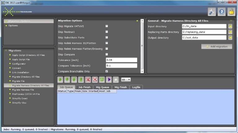
Figure 2. Enterprise Data Manager tool
After the alpha release, it was recommended to allow the users to “skip” specific functions in the process. This included “restrict”, “substitute parts”, “relink harness 3D/flatten or drawing”, and also “validation/compare.” This was very helpful to understand bugs, enhancements or user errors in the debug mode. As LMC ran several scenarios, they allowed for isolating any existing problems through the migration steps. The first step in the process was to ensure the file was extracting the CATIA V4 file correctly, which included the linked backshells, flatten parametric, and support orientation. David Selliman recalled, “I found a bug where the script would pull the standard parts from LMC database, with full parametric from CATIA V5 to replace the standard parts from CATIA V4 and it failed consistently. This time-consuming bug was a simple fix, but LMC needed to have the reading of CAITA V5 with features in its license configuration to complete this step and move on to the next process. Fortunately, CoreTechnologie feature-based reading technology reads the CAD file from the binary code without access the API from Dassault CAD systems.”
When the beta release was provided, LMC moved the process on to a more powerful machine to speed the testing process as well as to run more complex files through the process. At each step of the process, a file folder was created with a “.toinst” extension. This file was deleted when the next step had been completed. The file is used by LM_link_installation script. The results and logs had a folder for each process shown in Figure 3 (blue folders).
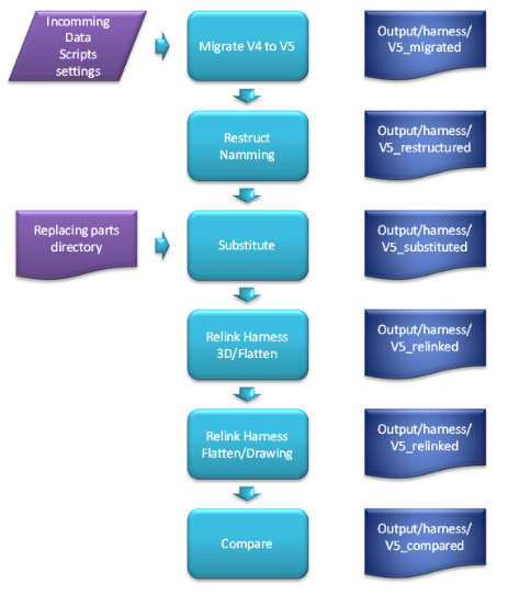
Figure 3 – Data log folders
In the case that the resulted folder had a failure; as an example – the link between the 3D and flattened data is not correct you will find in the output/harness the V5 relinked folder a file with the “.tofix” extension. This must be fixed, then the above step can be retried with the usage of a skip step if not needed. During the migration and within the link installation, LMC could change migration tolerance (in inches or metrics).
With a success of 90 percent of the data migrated to CATIA V5, there were some post processing activities that still needed to be addressed. As an example; the bundle segment definitions-bend radius algorithm needed to be selected by slack, length, bend, and straight bend. Further, protective coverings tend to get linked or form extremity points that were incorrect. With that stated, LMC may not require that all the data be migrated after the dataset post process within the EDM.
As LMC was pleased with the timeline and the results of the migration of the F13, they decided to include the F35 in the migration tool developed by CoreTechnologies.
Migration Lessons Learned
David Selliman reflected on some valuable lessons on the project:
“In our ‘Lessons Learned’ meeting and the ambiguous nature of the migration, we discovered that the proper settings in CATIA affect the outcome, and consideration of data management should have been addressed within the PLM early in the process. LMC and Coretechnologie should have addressed the verification of the E3D data and removal of unnecessary details – the percentage of the migration would have increased. And as always, any successful project should embrace the technology, resources, and process with strong communications that assist in understanding failures. We believe that training should have been done along the way and more frequently.”
For more information, contact David Selliman at [email protected], or phone 810.923.6481