


By Igor Murokh – Tri-Star
According to IOP Handbook of Laser Technology, in 1999 approximately 22,000 laser marking machines were in use in various industries worldwide. Hexa Research expects overall laser market to reach $3bln USD in 2024. It seems quite possible that in a few years everything that needs to be marked will be marked with lasers including fruits and vegetables and most definitely wires and cables.
This article describes the basic principles of UV laser marking of wires and cables for aerospace industry and its applicability to other markets.
Direct printing on wires and cables with Ultra-violet (UV) lasers has been extensively tested and accepted within the aerospace industry both by OEMs and by the end users. It is covered by several documents and standards issued by SAE International (http://www.sae.org/ AIR5558, AIR5468B, AS5649) and reflected in the production specification of large and small frame aircrafts for commercial, industrial, and military use. The OEM list includes Boeing, Airbus, Lockheed Martin, Sikorsky, Gulfstream, Bombardier, Pilatus, and many others. It is also used by governmental agencies such as DOD, NASA, FAA, etc. End users employ UV laser marking machines during scheduled maintenance and repair procedures.
UV lasers leave a permanent indelible high-resolution mark on the substrate surface. To understand the phenomenon, we must consider how a laser beam interacts with material. For example, the beam can be completely reflected from a surface, as a sun ray from a mirror, or propagate unaffected, as a sun ray through clear glass window. In these cases, no trace will be left on a surface. To mark a material, at least part of the laser radiation must be absorbed directly on or near the material’s surface.
Depending on laser and material properties there are a few possible scenarios (Fig.1):
- The irradiated material evaporates, leaving relatively sharp border trenches on the surface.
- The irradiated material melts and spills from the inside out, creating hills and valleys in the middle of a plain.
- The irradiated material heats up and produces gaseous components that react with atmospheric oxygen, depositing a product of combustion (such as soot) on the surface.
- Color change. The material changes color without any other visible surface modifications.
- All of the above.
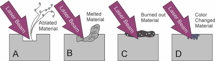
Fig.1. Laser-Surface Interactions.
Ablation is the cleanest way to alter the surface but provides low marking contrast because the affected area does not change color. Making deeper and wider marks improves legibility but reduces material integrity that is clearly unacceptable for aerospace applications. One possibility is applying additional layer of wire insolation and then selectively removing it exposing the undercoat of a different color, but this does not look very practical either.
Melting and burning marking processes are subject to long-term durability problems because the melted material and burned-out deposit may not stick well to the unaffected area. That resembles a 21st century hot stamping technique. Of course, this version is more advanced, flexible, and precise but it is still hot stamping with all its well-known deficiencies.
Color change can be an excellent solution under the conditions that it does not alter the material properties, provides sufficient contrast, good durability, and long-term stability. UV laser marking of aerospace wires and cables satisfies all these requirements.
Fig.2 shows ETFE, and PTFE insulated wires processed with Tri-Star Technologies M-100L-FG wire marking system. Well defined, legible prints stay intact even after extensive accelerated thermal aging.
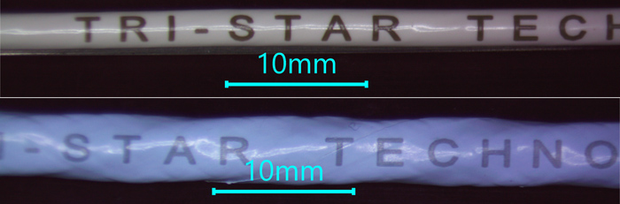
Fig.2. UV laser marking on ETFE (top) and PTFE (bottom) wires.
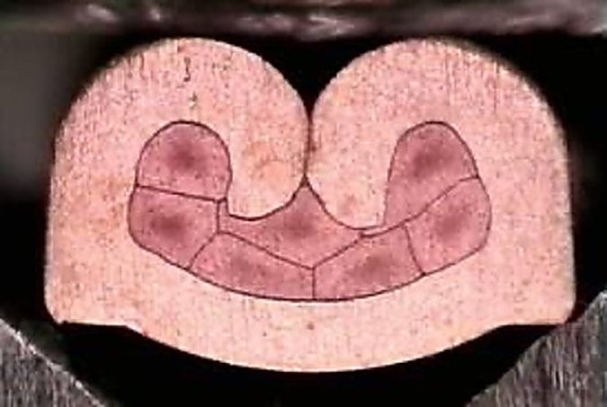
Marking cross sections (Fig.3) confirm that darkening zone extends 10-20um under the surface ensuring that marking cannot be altered or removed without physically destroying the top layer of the insulation.
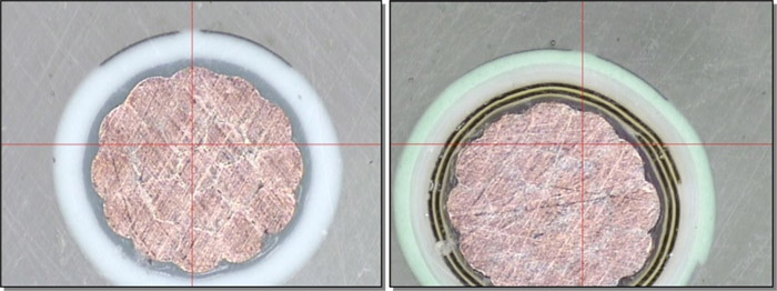
Fig.3. Marked wire cross sections for BMS13-48T10C01G022 (left) and BMS13-60T44C01G022 (right).
The question is how a light-colored polymer surface turns dark under laser exposure without burning or melting. The answer is magic substance called Titanium Dioxide (TiO2). Luckily enough, this is a commonly used pigment that wire manufacturers use to make insulation look white or otherwise light-colored, such as gray, blue, green, yellow, pink, etc.
An optical band gap around 3.1 electron volts accounts for TiO2’s intense absorption of UV radiation with wavelengths shorter than 380 nanometers. Irradiation with a UV laser permanently turns TiO2 particles from white to blue/black. The same effect occurs when those particles are embedded into a substrate. Ideally, laser radiation does not react with the base material and passes freely through the substrate surface. In contrast, the pigment particles within the substrate interact with the laser beam that modifies the particles’ structure and appearance, including color. For example, thin PTFE films are practically transparent to the UV light while small (~0.3u) TiO2particles randomly distributed through the insulation layer strongly absorb the light and change color.
Fig.4 illustrates the process in space and time. An incident laser beam penetrates freely through the first material layer losing a small fraction (e.g., 1%) of its total energy on interaction with originally white TiO2 particles, turning them black. The same happens on the second layer and so on until most of the laser pulse energy is absorbed within the top 50-100 layers. In reality, the process is quite limited both in time and space as total pulse duration is normally below 30ns and marking depth does not exceed 50um or so.
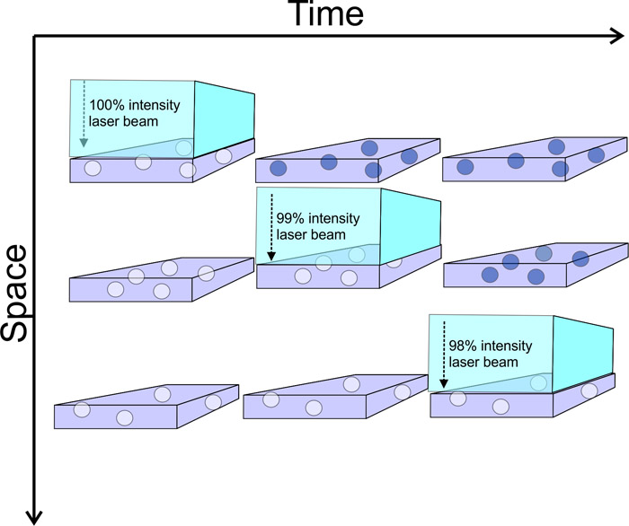
Fig.4. Schematic representation of UV laser beam path through a transparent media dopped with TiO2 particles.
Short nanosecond laser pulses prevent regular heat exchange between the additives and the surrounding material, limiting any structural and/or chemical modifications to the pigment particles themselves. Clearly this mark cannot be easily removed as most of it is distributed through the top layer but not on the very surface.
The question of what exactly happens to TiO2 particles under intensive UV light exposure is outside of the scope of this article, but the resulting change of color is irreversible. For example, long-term stability of UV laser marking on TiO2 doped ETFE films was investigated in McDonnell Douglas Research Laboratories in 1990. The marking showed little change during either thermal aging (770 hours at 229oC) or simulated solar irradiation (equivalent to 17 years of UV exposure in the Arizona desert).
The marking contrast is proportional to TiO2 concentration; however, excessive amounts may damage the insulation. Normally 2-4% by weight is enough to achieve a good contrast. Table 1 specifies typical contrast levels achievable by direct UV laser printing on the wire constructions commonly used in the aerospace industry.
Table 1. UV Laser Markable Wires and Cables
| Wire Specification | Color | Insulation | Marking Contrast |
| BMS 13-48 | White | Extruded XLETFE | Excellent |
| BMS 13-58 | Gray | PTFE Tape wrap | Good |
| BMS 13-60 | White | PTFE Tape wrap | Good |
| BMS 13-60 | Green | PTFE Tape wrap | Marginal |
| M22759/05,06,08 | White | Extruded PTFE | Poor |
| M22759/07 | White | Extruded PTFE | Marginal |
| M22759/09,10,11,12, 20,21,22,23,28,29,30,31 | White | Extruded TFE | Marginal |
| M22759/16,17,18,19 | White | Extruded ETFE | Good |
| M22759/32,33,35,41,42,44,45,46 | White | Extruded XLETFE | Very Good |
| M22759/34,43 | White | Extruded XLETFE | Excellent |
| M22759/80,81,82,83,84,85,86,87,88,89,90,91,92 | White | PTFE Tape wrap | Good |
| M85485/5,6,9,10 | Violet | Extruded XLETFE | Very Good |
| M25038 | White | PTFE Tape wrap | Poor |
| M27500 SP2S23 | White | Extruded XLETFE | Very Good |
| M27500/20 L3T08 | White | Extruded PVDF | Excellent |
| M27500/20 P2G23 | White | PVC/ NYLON | Very Good |
| M27500/22 C1G23 | White | PVC/GLASS/NYLON | Very Good |
| M27500/22 SP5S23 | White | Extruded XLETFE | Very Good |
| M27500/24 C3G23 | White | PVC/GLASS/NYLON | Very Good |
| M81044 | White | Extruded PVDF | Excellent |
Other wire types can be marked as well for as long as they contain the magic pigment. The requirement of having TiO2 in the outmost layer of a jacket is the primary limitation for the marking technology described above. In most applications, TiO2 is used as a white pigmenting agent and it turns black upon UV laser irradiation. Therefore, only light-colored wires can be legibly imprinted.
The rest of the wires can also be marked with a laser via the different mechanisms depicted in Fig. 1. However, these marking most likely will not be in compliance with strict aerospace standards unless we find another magic pigment that, for example, turns white from black upon the green laser exposure.
Tri-Star Technologies is happy to evaluate customer samples and can generally turn them around in a day or so. If you would like to submit samples for testing, please contact Tri-Star Technologies at (310) 347-5767 or [email protected]. Check out Tri-Star’s wire marking, crimping, and plasma treatment equipment at www.tri-star-technologies.com.
Igor Murokh, Ph.D.
Senior Scientist
Tri-Star Technologies
1111 E. El Segundo Blvd.
El Segundo, CA 90245, USA
About Igor:
Igor Murokh received his Ph.D. in Thermophysics and Molecular Physics from Luikov Heat and Mass Transfer Institute of Belarus in 1991. He has worked at Tri-Star Technologies, since 1994, developing plasma treatment and laser marking systems for the aerospace, medical device manufacturing, and pharmaceutical industries.