


By Jo Bimson
Most automatic harness test systems offer 2-wire or 4-wire resistance measurement capabilities. Some systems also offer dual-wire measurements, offering flexibility to use whichever of the two methods is most suited to the specifications of the item being tested, normally called the Unit Under Test (UUT). A UUT may be a single wire, a component part, a sub-assembly, or the final product.
To determine whether the 2-wire or 4-wire testing method is the most appropriate for your UUT, you need to understand how each one works.
2-Wire Resistance Testing
The 2-wire testing method simply means two wires are used to connect the measurement equipment to the UUT.
To measure the electrical resistance of a component, or UUT, an electrical current is passed through it. The current flowing through it is, measured in Amps (A) and the voltage across it is measured in Volts (V). As the voltmeter (shown in green in figure 1) has a very high resistance, only a negligible current flows through it, so the current measured by the ammeter (shown in red) can be considered to be the same as the UUT current (shown in blue).
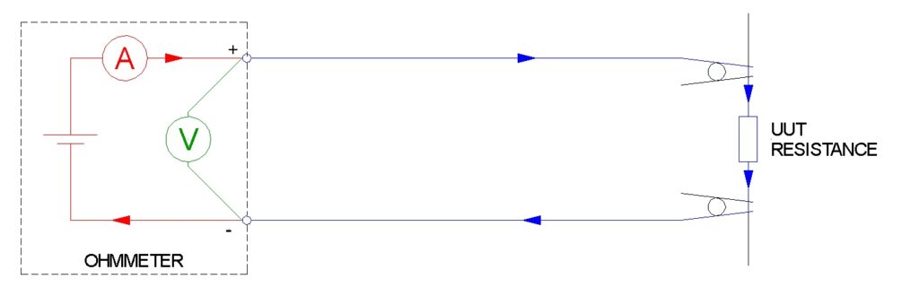
Figure 1. Measure of electrical resistance.
The resistance can then be calculated in Ohms (Ω) using Ohm’s law (figure 2).
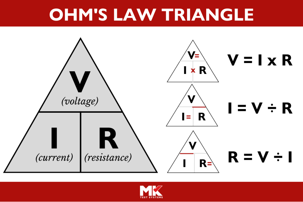
Figure 2. Ohm’s law.
In the real world, the wires (or interface) used for the connections also each have a small electrical resistance, so the actual circuit is as shown below in Diagram 2. Note: The Ohmmeter represents the test system, such as MK Test’s Automeg ®.
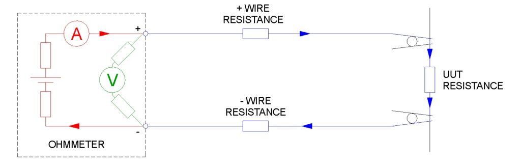
Figure 3. 2-wire resistance testing.
The voltage measured is the sum of the voltages across the UUT and the two wires feeding the current. This is shown in blue in Diagram 2 above. So, the calculated resistance is the resistance of the UUT, plus the resistance of the + wire, plus the resistance of the – wire.
In an Automeg, 2-wire testing would require two points of connection to two test points. MK Test’s MKAT ® software can allow for the extra resistance of the interface wires by subtracting an offset value from the measured resistance and reporting the result.
For this reason, the 2 wire method is suitable for most applications where the resistance must be measured to an accuracy in the order of Ohms.
4-Wire Resistance Testing
To measure resistance with greater accuracy, the 4-wire method can be used. This requires four wires to be connected to the UUT, as shown in red and green in Diagram 3 below. The means that the current has the same path through the same resistances, but the voltage is measured directly across the UUT.
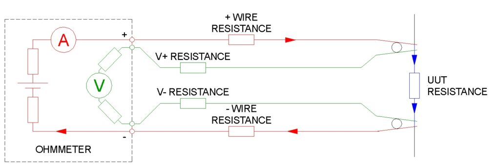
Figure 4. 4-wire resistance testing.
As the voltage measured is that which is across the UUT, the calculated resistance is the exact resistance of the UUT. Therefore, this method can be used to measure resistance in the order of milli-ohms or micro-ohms.
Summary
In summary, 2-wire resistance testing is a simpler form of measurement than 4-wire testing. It provides measurements accurate to Ohms. In contrast, 4-wire testing uses twice the number of test points, but provides a much greater level of accuracy.
The Automeg range of test systems offers models dedicated to 2-wire or 4-wire testing, but the most popular models are those that offer both modes. Many test applications can use the 2-wire method for the majority of connections to be measured, and 4-wire for certain connections which require higher accuracy.
Want to learn more?
Want to join a free webinar training session on this topic? Go to the Webinar page under the Support tab at mktest.com.
Jo Bimson Principal Systems Engineer at MK Test Systems.