


Testing electrical cables at high voltage helps to identify the presence of moisture, solder flux, or contamination that may have penetrated breaks in the insulation or connector backshells, and ensures that the insulation between wires can sustain temporary voltage excursions higher than the normal operating voltage without breakdown. The result of a high voltage test typically shows the insulation resistance between wires in the hundreds of megohms or higher. Test specifications requiring insulation resistance of five gigohms are not uncommon.
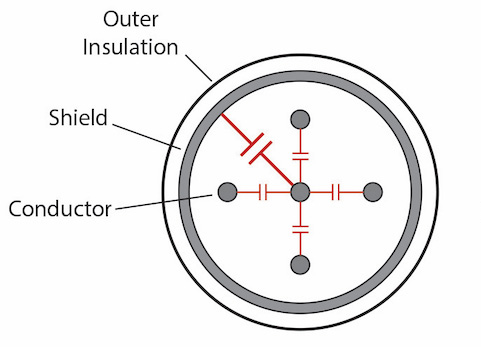
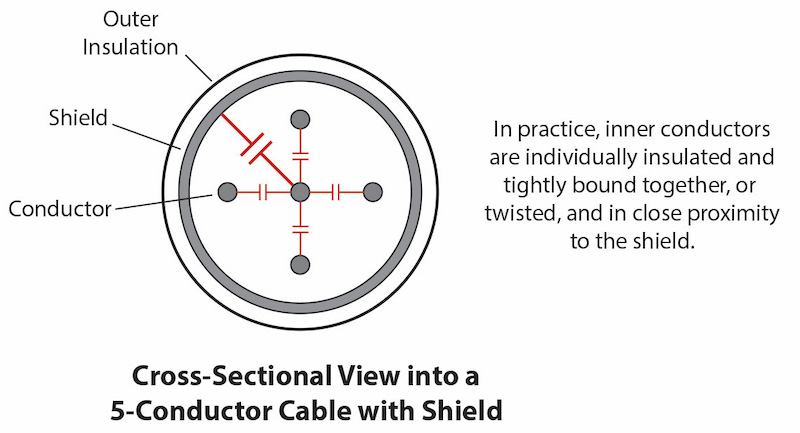
Many high-reliability cables include a woven shield surrounding all conductors. The shield prevents external electrical interference from coupling to signals on the internal conductors, and blocks electrical noise that may be generated by normal signals on the internal conductors from radiating into the environment. Shielded cables, however, complicate a high voltage test because of the greatly increased capacitance a shield presents with respect to the inner conductors. Because of the much greater surface area of a shield when compared to a wire, the capacitance between the shield and conductors increases proportionally. Capacitance increases even further with cable length.
With increased capacitance, the energy stored by a charged shield also increases to levels that may be hazardous to the operator, and may damage the cable’s insulation due to arc heating should an insulation breakdown occur. Note that energy stored in a capacitor increases directly with the capacitance, and with the square of the voltage:
E = ½ CV2
Many test specifications require the shield to take part in a high voltage test as an additional conductor. The statement below comes from a typical specification:
Assemblies shall exhibit an insulation resistance of no less than 500 MΩ at a test potential of 500 Vdc applied between the shield and conductor.
Automatic high voltage test equipment will apply DC voltage to one conductor while all other conductors remain at zero volts. Normally for each wire, the voltage ramps up gradually, holds for the “dwell time”, and ramps down once the test on that wire finishes. This process repeats for each conductor in the cable, so for example, a five conductor cable, the upramp-dwell-downramp cycle would repeat five times, each time on a successive wire. Through this process, a wire’s insulation is actually tested twice, once when the wire itself receives the high voltage (+ to – polarity across the wire’s insulation), and once when the same wire remains a zero volts while another wire receive voltage later in the test (– to + polarity on the first wire).
When we include a shield in the test, it represents just another “wire” in the cable and follows the same process. In this case, when voltage is applied to the shield with all other wires at zero volts, the shield holds much more charge than when voltage is applied any one wire with the shield at zero volts. With the greater charge on the shield, much more energy is stored in the shield than in a wire, and an inadvertent discharge through an insulation breakdown or human body contact will result in considerable current flowing. This may, in turn, melt a pinhole in the insulation, rendering the cable damaged and unusable, or worse, create a dangerous electric shock hazard to an operator if the discharge resulted from human body contact. Even the act of charging the shield on an upramp may exceed the tester’s trip current (a preset current limit representing a breakdown) before the test voltage is reached.
Typical polymer plastics used in wire insulation prevent current flow equally well with the electric field vector in any direction. We would see, then, that between any two wires, the insulation functions with identical leakage resistance whether we apply high voltage to wire A while we hold wire B at zero volts, or the reverse. Because the shield, considered as a conductor, would normally be tested in both directions, we can avoid the heightened risks of pinhole insulation damage and electric shock by not applying high voltage to the shield, while still applying high voltage to each wire with the shield held at zero volts through the duration of the test. Doing so will in no way reduce the efficacy of the test.
Referring to the test specification given earlier, applying 500 Vdc between the conductor and shield tests the insulation just as well when applying it between the shield and conductor. So, by testing only between the conductor and shield, we eliminate the risks associated with applying voltage to the shield.
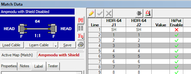
In the CableEye® tester manufactured by CAMI Research, any conductor may have high voltage suppressed during test by simply denoting this in a “HiPot Enable” column. In this screen shot, we show how to suppress high voltage being applied to the shield:
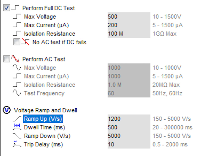
A shielded cable may still pose a problem when testing at high voltage even if we do not apply voltage to the shield simply because the conductors themselves will store increasing amounts of charge as cable length increases. Typically, in this situation, the charging current during the upramp may approach or exceed the normal trip current. Compensate for this be lowering the ramp rate so that the instantaneous charging current never reaches the trip current. This shows how it’s done with the CableEye tester. In this screen shot, we reduce the upramp from 5000 V/s to 1200 V/s:
Some cables have multiple groups of shielded wires combined in a single bundle such as shielded twisted pairs, or bundles of coaxial conductors woven into a single cable. When internal shields are ganged together and high voltage is applied, capacitance problem becomes even more extreme. In addition, the leakage reported is the sum of all of the leakages between the parallel shield buses and the wires they are shielding. It is likely that this sum will exceed the permissible leakage and cause the computed insulation resistance to be too low resulting in a failed test, especially if there are a large number of shields ganged together. The average leakage is, of course, the sum of the leakages on the grouping divided by the number of conductors in the grouping. The more wires the shield encompasses, the greater the leakage (normal) and the lower the total insulation resistance of the group.
For reasons explained above, as long as the shields remain at zero volts when the other wires are tested at high voltage, it is not necessary to apply voltage to the shield conductors to accurately test insulation resistance. When the high voltage is suppressed from all of the shields, the cable will not fail due to unnecessary summing of the leakages.