


Testing Appliance Cables & Connectors
Overview:
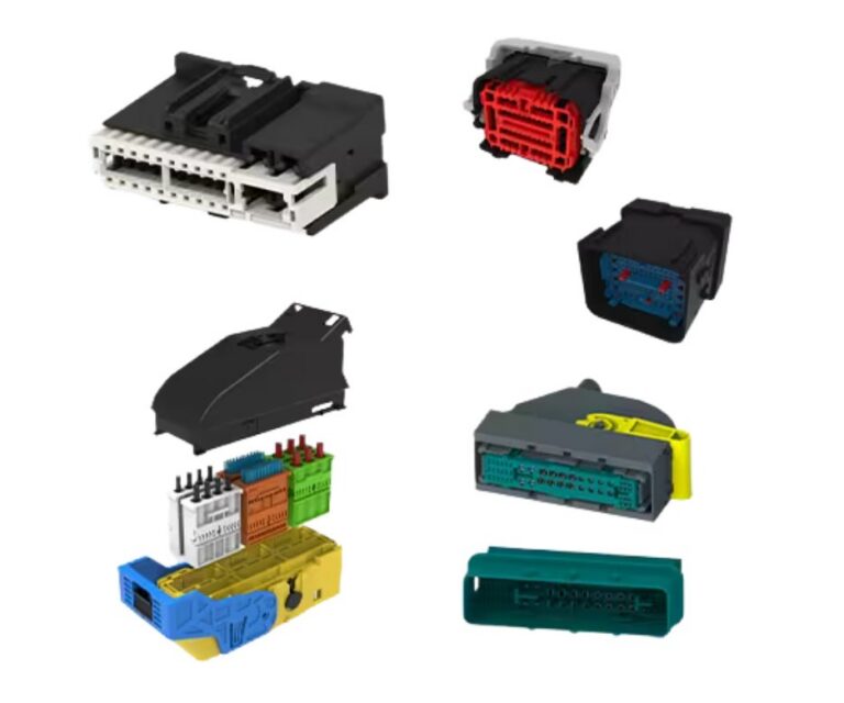
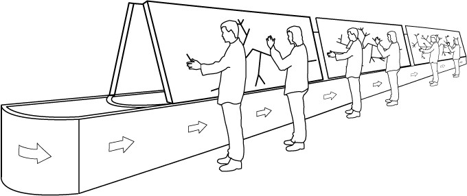
Driven by the desire for higher capacity appliances within the same external design envelope, and by the more complex functions, electrical design is being steered towards more and more compact solutions – solutions that include combining signal and power lines within a single connector, and reducing the pitch of board connectors.
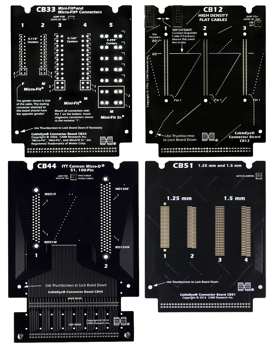
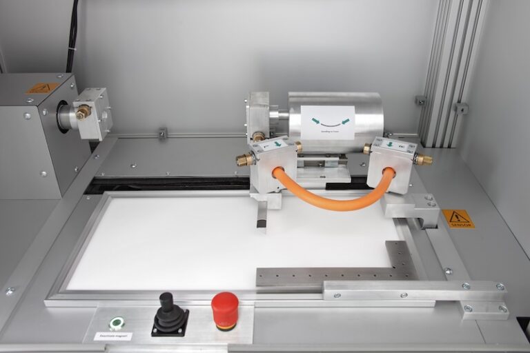
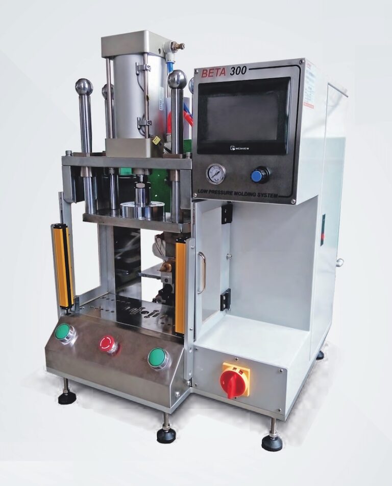
(Fig 1: Test fixtures accommodate connectors of different types and pitches.)
Consequently, micro-pitch connectors are seeing greater use in appliance board-to-board and board-to-cable interfaces and with narrower pitch comes a higher probability of shorts.
Smaller gauge wires are more difficult to insert, and combined with well-documented contact locking lance issues there is greater chance of continuity breaks especially when Connector and Terminal Position Assurance devices are neither features of the design nor of the chosen connector.
Additionally, some high performance high-density board-to-board connectors incorporate a ‘floating’ design that mechanically absorbs alignment errors thereby reducing stress & solder cracking. These floating contact systems can move in two lateral axes by as much as ±0.6 mm. During the operation and life of the appliance, there is a probability that this floating contact may move. How can continuity be verified across the full range of available motion?
Testing continuity & HiPot using multiconductor cable testers is an essential part of the workflow. Thorough testing prior to and after installation reduces the likelihood of appliance failure including catastrophic events such as fire and flooding. It is simply not sufficient to rely on “glow-wire” specifications to prevent fire.
In this article, we introduce a basic understanding of what ‘thorough’ continuity and HiPot testing entails.
Continuity Test
1 – Traditional Test
The traditional basic continuity test checks for opens and shorts at an instant in time only. The limitation of the traditional approach is that the result is only true for the test object as it was presented in physical location/orientation at that instant. Let’s consider a connectorized cable. If such a test was performed yielding a ‘PASS’, it cannot be assumed that the same would hold true when the cable is moved to other points through its full range of motion. Defects such as broken wires, cold solder joints, and bad crimps can cause intermittent failure.
The danger is that companies relying on the Traditional Test are at risk of installing defective cables in their appliances. This result, at best, in appliance failures that frustrate the end-user and, at worst, in a major malfunction or catastrophic event such as a fire.
2 – Enhanced Test
To check continuity thoroughly, an enhanced test should be performed that additionally scans for both intermittent and miswire errors (Table 1).
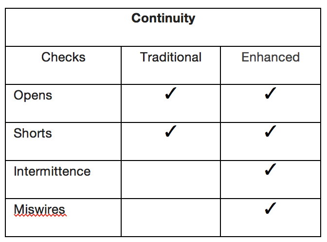
(Table 1: Traditional vs. Enhanced Continuity Testing)
These can be measured fast (in the ‘blink of an eye’), simultaneously across all conductors, and in a manner that clearly identifies the type of error as compared to a desired design known as a ‘Golden’ or ‘Master’ cable (Fig. 2). The graphical result of Figure 2 illustrates a multiconductor cable with two faults – an open (yellow), and a miswire (yellow-red stripe).
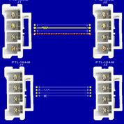
(Figure 2: Screen shots of cable with TE PTL connectors a) continuity test result (top) and b) golden cable (bottom). Test result overlays desired design, and highlights type and location of error – open (yellow), miswire (yellow-red striped). Note: A short, if present, would show as a solid red line.)
In this particular case pin 4 has been wired to pin 4 (correct locations) but without the specified inline component (a diode) so causing a miswire to be flagged. Note that correctly wired sockets and plugs will also show up as miswire faults if they have been connected to each other out of specified orientation. Knowledge of the type and position of error provides useful feedback to process improvement engineers and QC.
Connector pins that are not fully seated cause intermittent opens, while conductive debris is often the source of intermittent shorts, especially with micro-pitch connectors. These faults might cause intermittent power disruption to a motor resulting in motor damage, or signal a solenoid to switch the wrong valve or the right valve at the wrong time perhaps delivering bleach or hot water instead of cold, or even causing a flood by not switching off the water.
Testing for intermittent faults is very easy – an operator (or fixture such as a design verification ‘shake’ table) flexes the cable while a continuous stream of test pulses sweep through the full set of test points. Errors are detected and identified only when a test pulse coincides with an intermittent event – an event that itself may be fleeting. Because of this, the test engineer adjusts the cycle frequency so as to capture the most fleeting, random event. The intermittence test of Figure 3 shows that 1.4% of the 434 test cycles (set at 100ms/cycle) coincided with an intermittent even.
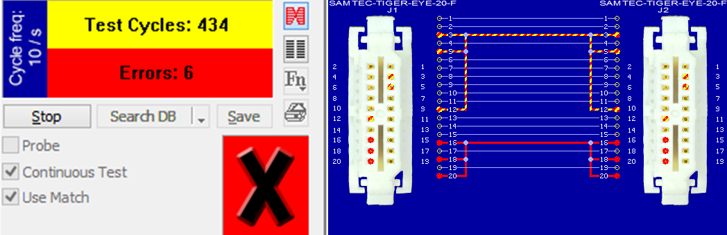
(Figure 3: Screenshot of an intermittence test on a cable consisting of Samtec 0.80 mm pitch Tiger Eye™ connectors with discrete wires. An intermittence test allows for adjustment of the cycle frequency test parameter to improve the likelihood of ‘capturing’ an intermittent event. This cable failed the test – 6 error events were detected while the cable was being continuously flexed. Two issues were identified – an intermittent open (solid yellow line) and an intermittent short (solid red line.)
Clearly, the intermittent fault was hard to trigger and/or was so brief that events tended to occur ‘between’ the test pulses. However, it takes only one detected event to fail the cable ensuring that you produce only quality product of high reliability. Bear in mind that this is a multiconductor test and PC-based cable testers such as CableEye® can perform 64 test point intermittence testing at 11ms/cycle over any duration. Being so fast and efficient, and given that there is no additional set-up time compared to a static continuity test, there is no reason to exclude a check for intermittent errors.
The same test process can be used to verify board-to-board connectors with floating designs with the intermittence test being performed while the connector is moved through its full adjustment range. Design verification data (http://suddendocs.samtec.com/testreports/tc1023–3438_report_rev_2.pdf) suggest that between 2 and 9 lbs force is needed to move these connectors to their maximum range. The motion could be applied manually or through a microcontrolled jig for improved repeatability.
High Voltage Tests
1 – Test Portfolio
Insulation integrity is verified with High Voltage (HV) tests and can be carried out with ac or dc voltages. In either case, the test calls for the applied voltage to far exceed the specified operating voltage. For safety reasons, HV tests are performed only after successful completion of continuity testing. These tests consist of checking the Dielectric Withstand Voltage (DWV) and the Insulation Resistance (IR) and reveal design and manufacturing faults such as insulation pinholes and the presence of gap-bridging moisture. A passing device will be proven to have insulation capable of protecting the consumer operator even during power surges.
The same HV tests can also highlight issues with the sharing of signal and power lines within the same connector, and within connectors of compact pitch.
2 – From Two-Terminal to Multiconductor
Modern PC-based cable testers can readily switch between testing two terminal components (such as transformers) and multiconductor cables & harnesses – and for voltages up to 2100Vdc/1200Vac. Figure 4 depicts a transformer under test with a screenshot of the near instantaneous result – DWV (top), IR (middle), Leakage Current (bottom). Leakage current measurements are especially useful when determining whether borderline DWV or IR results are really an issue. The same user interface appears and test principles apply when HV-testing multiconductor set-ups. In this case, the cables connect to the tester via interface boards (such as seen in Figs. 1 and 4), or via interface ‘harnesses’ such as an Ampmodu cable.
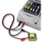
(Figure 4: HiPot Test | Leakage & Insulation Breakdown | 2-Terminal Devices)
In-Plant Scenarios
1 – Design Verification & Prototyping
Thorough testing of a product starts at the Design Verification and Prototyping phases. Early feedback of the results allows for improved Design for Manufacturability and saves money by catching problems sooner in the workflow.
Typically, harnesses and cables destined for systems such as appliances, are tested within an environmental chamber where the rigors of transportation and a life of operation in a variety of operational temperatures, humidity, and vibration can be simulated. The same PC-based testers used for Continuity and HV tests on the production line are flexible enough to be integrated into these test systems, and can accommodate long test interfaces between the tester and environmental chamber electrical ports (to which the cables under test within the chamber are connected).
The prototyping stage is also prime time to develop test automation processes for the production line.
2 – Test Automation
For efficient testing, many manufacturing engineers prefer to automate Continuity and HV testing. With PC-based testers, they are able to incorporate external relay boards to automatically switch between different circuits during test, or to operate lock & release latches; use API or LabView interfaces to integrate with other equipment; scan ID badges for operator log-in; scan work orders for automatic tester set-up; connect foot pedal or remote controls and a variety of audible and visual Pass/Fail external indicators (such as tower lights).
The test procedure itself is written in a simple scripting language and includes calls to automatically log the test data for statistical process control, and to print graphical test reports for internal or customer use. An example of this procedure, a macro, is given in Fig. 5 that can be triggered by the inbuilt test pushbutton, or a peripheral such as a footswitch, or relay closure.
(Figure 5: Macro example – (Line 1) Load specific cable from database. (2) Pause to mount cable & press test pushbutton when ready. (3) Measure cable. (4,5) If test data and match data agree, (6) sound single tone and (7) repeat from line 2. (8) If the data disagree, search the database for match. (9) If match is found, then 910) print match data wiring, netlist, notes, and laebl and (11) restart from line 1 to reload the original cable file. If the database does not contain a match, (12) sound a double tone and (13) end the macro.)
Summary
Modern appliances are calling for smaller volume electrical designs yet with greater functionality, resulting in systems that must be more carefully checked for continuity and insulation integrity – incorporation of smaller pitch connectors brings a higher chance of faults.
An enhanced continuity check has been discussed that tests for opens, shorts, miswires, and intermittent faults, and high voltage tests to check insulation integrity were described. The same HV tests can also highlight issues with the sharing of signal and power lines within the same connector, and within connectors of compact pitch.
PC-Based Cable Testers are well suited to the thorough testing required for Appliance cables and connectors, including for design verification, prototyping, and automation.
® CableEye is a Registered trademark of CAMI Research Inc.