


In the testing of coaxial cables, one of the areas that is not well defined, at least from the initial evaluation perspective, is the impact that a bend radius has on the cable performance. Standards such as AS50881 specifically define the coaxial cable minimum bend radius should not be less than 10x the cable diameter. The rationale is to limit signal degradation from factors like conductor and dielectric stress.
The MIL-W-5088 standard was published on March 14, 1951 and established “requirements for the installation of wiring and related accessories for the interconnection of electrical and electronic equipment in aircraft.” The first instance of the 10x bend radius for coax cable came in 1982, and for the last 41 years, after more than a dozen updates, including a transfer of the standard to the SAE (and the renaming as AS50881), this value remains unchanged.
When these standards were created, the materials used in the coax cable construction were far less capable. Since that time materials have advanced, as have manufacturing processes. There are now materials that can better handle the mechanical stress of smaller bend radii.
Alternatively, the ASTM F2639-18 EWIS design standard does provide other guidance. In section 7.2.1.65, it states that the bend radius for coax cables should be no less than 6x the cable diameter. This divergence between standards is due to nothing more than a lack of recent data. In this article, test data from Lectromec’s lab is provided showing the performance impact of bend radius on coaxial cables signal attenuation.
TEST SETUP
A M17/128 RG400 coax cable was used for this assessment. This cable has a silver-plated copper conductor, extruded polytetrafluoroethylene (PTFE) dielectric, a silver-plated braided shield, and an extruded fluorinated ethylene propylene (FEP) jacket. Per the specification sheet, the cable’s maximum attenuation are as follows:
- 4.5 dB/100ft at 100 MHz
- 10.5 dB/100ft at 400 MHz
- 3.2 dB/100ft at 100 MHz
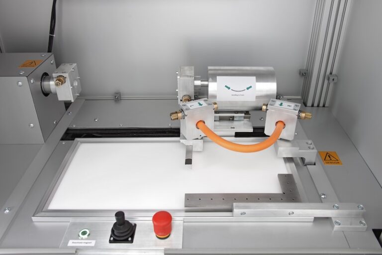
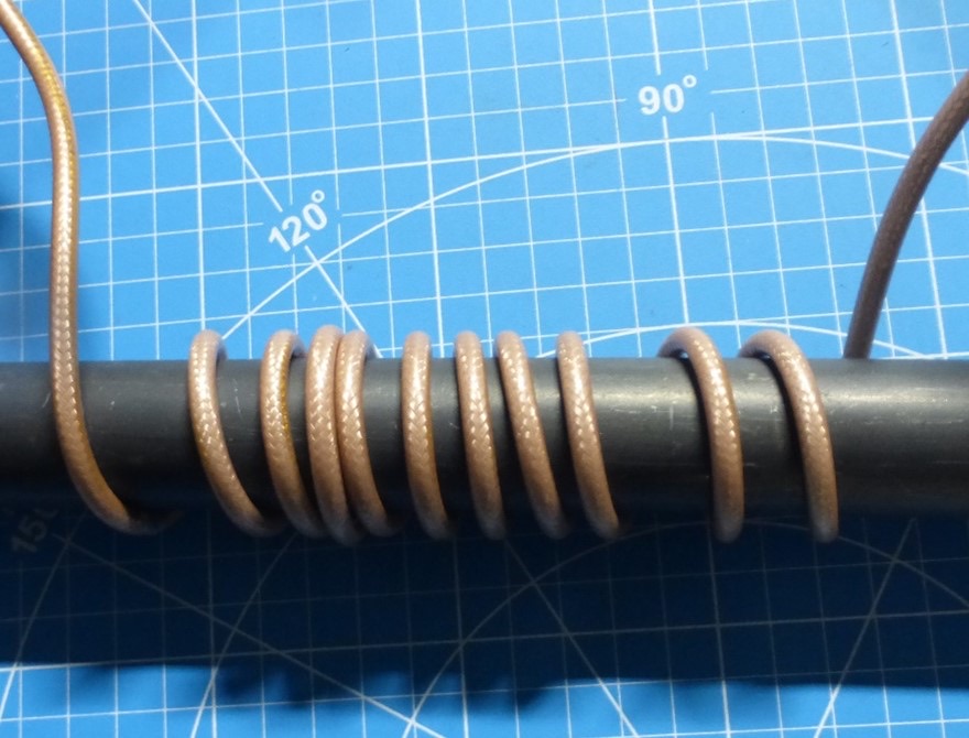
In this test setup, the MIL-C-17 coaxial cable was terminated with TNC type connectors and connected to a spectrum analyzer. After normalization, the spectrum analyzer swept across the frequency range from 100 kilohertz to 3.2 gigahertz. The prepared sample on the mandrel is shown in figure 1.
PROCEDURE
Four different bend radii were evaluated:
- No significant bend
- Bend radius of 10x cable diameter
- Bend radius of 5x cable diameter
- Bend radius of 3x cable diameter
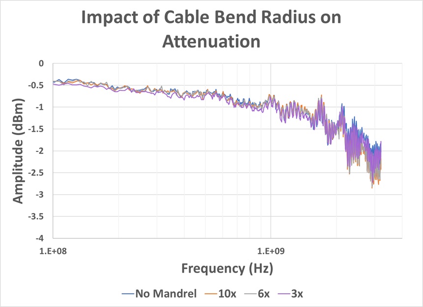
The cable was wrapped ten times around the mandrel with a short segment left straight to connect to the test equipment. The results are shown in figure 2.
CONCLUSION
The lower frequencies in the sweep show greater attenuation at tighter bend radius. The attenuation measurements and their corresponding product values, in dB, are as follows:
| Attenuation at Given Frequency | |||
| 100 MHz | 400 MHz | 1 GHz | |
| Max Spec Sheet Attenuation (Scaled to sample length) | 0.066 | 0.106 | 0.17 |
| No Mandrel | 0.066 | 0.103 | 0.13 |
| 10x | 0.063 | 0.103 | 0.12 |
| 6x | 0.063 | 0.103 | 0.13 |
| 3x | 0.074 | 0.129 | 0.14 |
Both the 10x and 6x bend radius performed well within the specified limits. However, a tighter bend of 3x shows values outside the acceptable range in lower frequencies.
There is little difference, if any, between the performance of the cable at 10x or 6x bend radius and that of the cable without a mandrel. This is not to suggest that all coax cables will perform similarly or, as seen here, that a tighter bend radius (3x or less ) would not have any impact, but data like this can be generated to support deviation from industry standards. The AS50881 guidance has been successful for so long that changing a value like the 10x bend radius is difficult. While the guidance is conservative, deviations can be made in specific cases where data is generated to support implementations.
The fact is that data is often something not readily available and the hope is that this showcases there are options and tools available to go beyond the industry standards. As this data becomes more available, it will help maintainers and designers as they consider how they route the cables on their aircraft and what testing they may need to verify the system performance.
Perhaps the M17/128 RG400 cable is unique in its performance under bend conditions, but it is more likely the case that newer constructions can perform better under tighter bend conditions. This testing was carried out on virgin samples, and how the tighter bend radius would impact performance after thermal aging is unclear (at least until Lectromec’s next article on the topic). These factors should be considered before accepting a tighter bend radius for any application.
If you are looking for testing to assess the performance of your cables or for the cables that you are looking to install on your aircraft, contact Lectromec.
Author – Megan Chambellan
Megan has been with Lectromec since 2021 and has been a key contributor on projects involving testing of EWIS failure modes, fiber optics, and high voltage EWIS certification testing. Her knowledge and attention to detail ensure consistent delivery of accurate test results from Lectromec’s lab.