


In the last issue, we took a look at different test methods for crimp quality and which errors they can help detecting. This article will focus on cross-sectional images of crimp connections on the example of open crimp barrel terminals.
Depending on the crimp contact variant, there are corresponding criteria that are used as a basis for evaluating a micrograph.
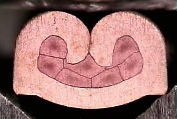
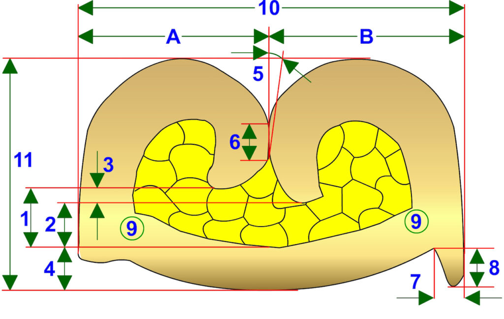
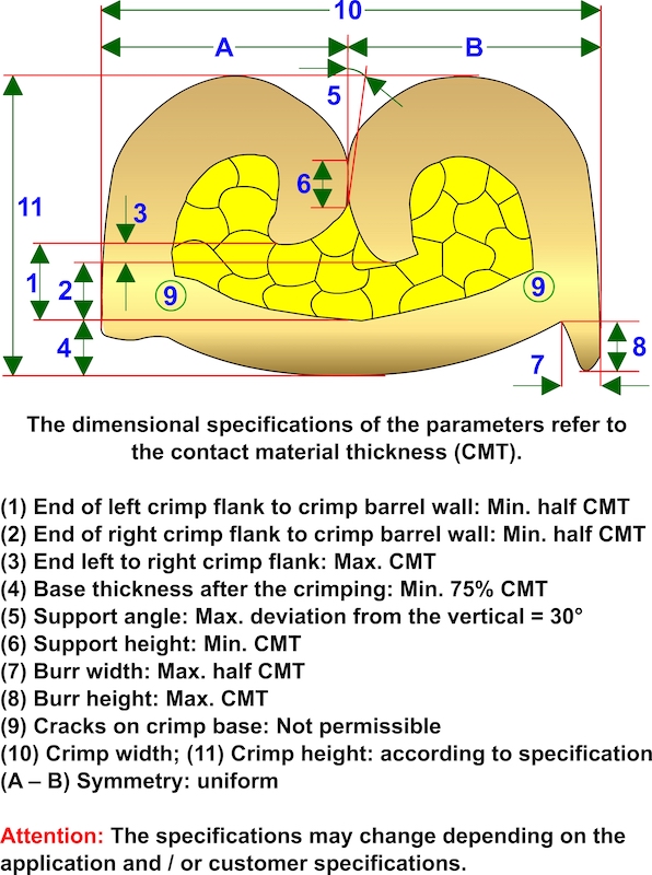
The basic characteristics of a good crimp always remain the same. Regardless of the crimp contact variants these are the following (see figure 1):
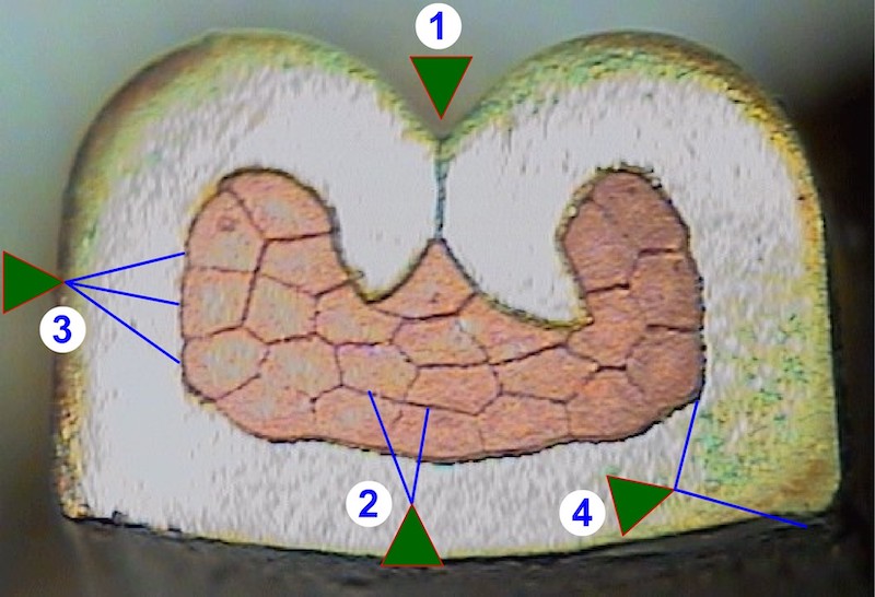
Figure 1. Basics of a good crimp.
(1) When sheet metal is deformed, the material tends to spring back to its original shape after the bending process. This effect also occurs after the crimp flanks have been rolled in. To counteract this, the crimp flanks must support each other.
(2) The compression shape: The conductor material in this example consists of copper. As soon as copper comes into contact with the ambient air, the surface of the individual wire strands oxidizes and forms an insulating layer. If wires are stored in a humid environment, this effect is intensified. By crimping the stranded conductor, the round individual wire strands are pressed together irregularly and in a honeycomb-like shape. The crimping process breaks up the oxide layer between the wire strands.
(3) If the crimping is optimal, the crimp sleeve will also show deformations!
(4) The crimp contact must not be damaged or have cracks on the crimp base.
Typical examples of error that in micrographs of open crimp barrels
Overfilled crimp – no mutual support of the crimping flanks (see figure 2)
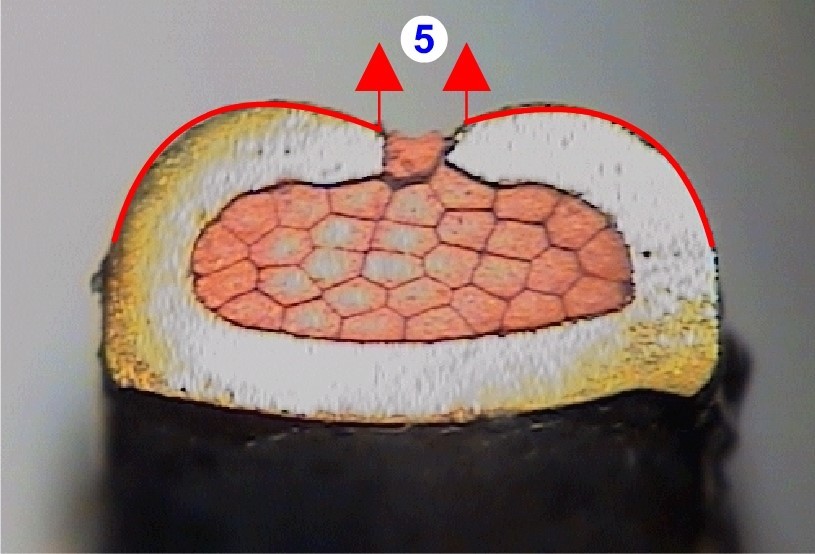
Figure 2. Examples of error.
The crimp flanks (5) do not support each other. There is a risk that the crimp flanks will open.
This impairs the mechanical and electrical properties of the crimp connection.
Thermal load (cold/hot alternation) accelerates the opening of the crimp flanks.
Cracks or large burrs on the crimp barrel (see figure 3)
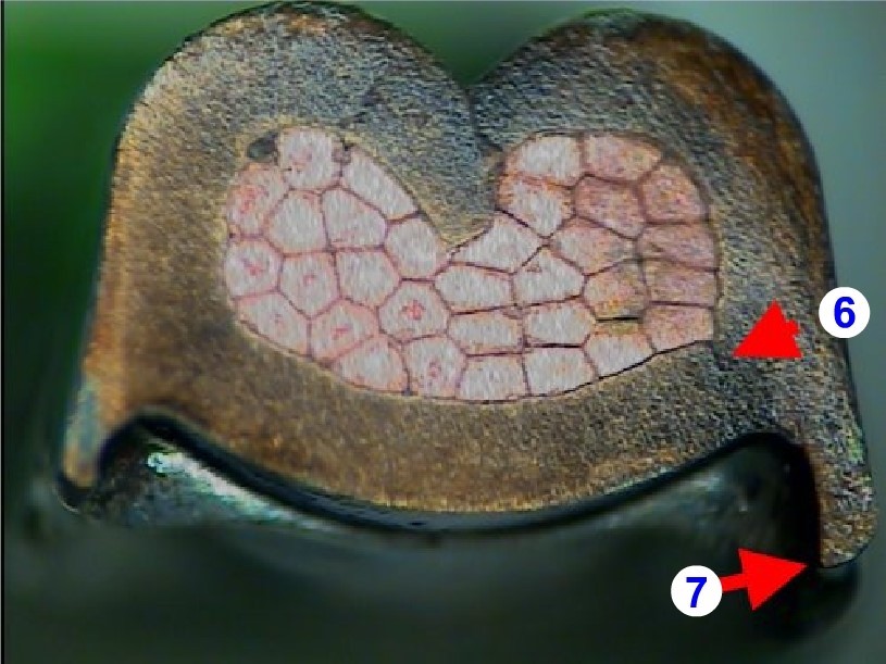
Figure 3. Further examples of error.
(6) Damage to the crimp contact (like cracks in the wall) is intolerable!
(7) The burr height must be smaller than the material thickness. The burr width must be smaller than half the material thickness.
Another cause of heavy burr formation is overpressing of the wire crimp area (crimp height too small). Severe burr formation (7) is a sign of damage to the crimp base (6). Damage to the crimp barrel impairs the mechanical and electrical properties!
Micrograph without a lab?
A micrograph tells you a lot about the inner structure of a crimp connection. But what if you don’t happen to have a micrograph laboratory and still need to check the insides of your crimped connection?
For optimum quality control of crimped connections, the use of a micrograph laboratory is one of the most important quality control instruments in wire harness production today. A micrograph provides important information about the degree of compression of the stranded conductor, the curling of the crimp flanks, damage in the wire crimp area and so on.
However, the cost of a micrograph laboratory is a major obstacle to the investment in this quality tool, especially for small-scale cable assemblers. Equipment for other tests, such as pull-out tests, can be found more often in smaller companies. The micrograph of a crimp, however, offers much better possibilities for evaluating the crimp connection in terms of quality and for troubleshooting. Those who attach great importance to quality should therefore consider budgeting for a micrograph laboratory sooner or later.
But what if there’s no budget right now, but you still need a micrograph?
For one, there are external providers, such as laboratories or system suppliers for wire processing machines, who create and evaluate a micrograph with a test report. The samples (crimped connections) are sent to them and after some time the results are made available. If you are not in an extreme hurry and can wait a few days, this can be a cost-effective solution. A great benefit of this approach is that this professional micrograph documentation can also be provided to your customer as proof of quality.
But the time component can also be a potential drawback under certain circumstances.Due to the mailing of the samples and the processing time for the preparation of the micrograph, it takes an average of a week until you can hold the corresponding results in your hands. And it may become really annoying when you then find out that your crimp connection is not OK and you have to optimize your crimping result by changing the settings of the crimping tool. Because who wants, or can afford, to interrupt production for a longer period of time?
So, what can you do when you need a quick statement about your crimping result? You could create a “rapid microsection.”
To do this, you will need a bench grinder with a coarse and a fine disc or, alternatively, a belt grinder. A hand grinder may also do the job. See figure 4 for details.
(1) You separate the crimp contact just before the wire crimp area e.g. with a saw. Please don’t use a side cutter, because it will squeeze and deform the wire crimp area, which must be avoided at all cost!
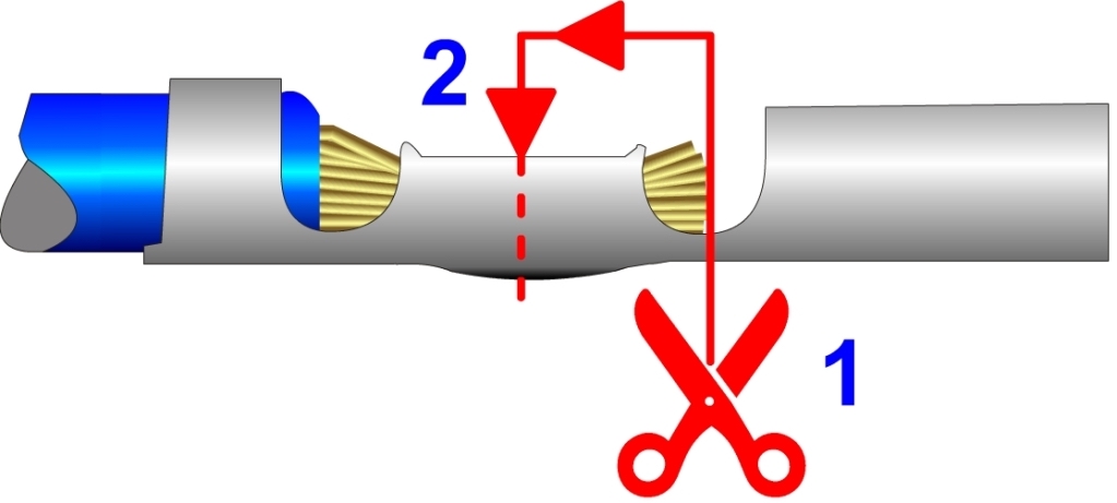
Figure 4. Rapid microsection.
(2) After cutting, grind the crimp contact on the coarse grinding disc up to about the middle of the wire crimp area. Then hold the resulting grinding surface briefly against the fine grinding disc (figure 5).
Make sure that the grinding surface is created at an angle of approximately 90°!
Please keep in mind: When separating and grinding the crimp contact, it must not be subjected to mechanical or thermal stress. Of course, these factors can spoil the result or make it useless.
So, make sure to pay attention to the direction of grinding and that no heat is generated during the process (e.g., cool frequently with water).
After cutting and grinding the surface, you look at the result and will notice that not much of the inner contours of the crimp connection can be seen. Consequently, you need to clean the cross-section (figure 6).
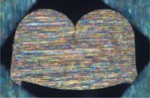
Figure 5. Microsection after cutting & polishing (grinding).
There are basically two possibilities for this: Some people use corrosive agents such as nitric acid which, however, represent a health hazard and are not recommended!
Rather, use electrolysis as a cleaning method. This considerably less hazardous method is a procedure well known from the cleaning of metal surfaces (like weld seam cleaning). You will find ready-made cleaning devices for crimp microsections on the market. Alternatively, the handcrafters among you may even want to look into building their own cleaning device.
And this is how the procedure works: Using a (preferably adjustable) 12 V direct current (DC) power supply, the crimp contact is connected to the negative pole via a clamp. A carbon fiber brush or staining pen is connected to the positive pole. The carbon fiber brush, moistened with the electrolyte (e.g. KCL 3M), is held on the surface to be cleaned and as long as the current flows, the cleaning process takes place.
With the aid of a potent magnifying glass or microscope, you can now see the contours of the crimp connection.
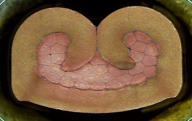
Figure 6. Microsection after cleaning
IMPORTANT: With a micrograph created in this way, you can only see the tendencies of your crimp connection.
- How are the crimp flanks rolled-in?
- Is there any damage to the the crimp barrel wall, like cracks or burrs?
- Are all wire strands captured in the crimp?
- Are all wire strands shaped irregularly?
- Are there any cavities in the crimp area?
Of course, this method is only a makeshift method that, if done correctly, can give an overview and bring major errors to light. Logically, it is not possible to take crimp measurements or obtain really reliable data or a test report. But it can, under certain circumstances, give a quick indication for the need to initiate further measures – in a fast and inexpensive way.
Not sure about how to evaluate your micrograph or need a second opinion?
Then send a picture of your micrograph to [email protected] and we will have a look at it. You will receive an evaluation within approx. a week. During the month of May and June 2023 we offer this as a complimentary service for WHN readers.
More information about the preparation of micrographs and examples of micrograph evaluation can be found here: https://bit.ly/3zT0mjx
This article was written by Volker Kratt, Founder of the German internet platform “KabelForum”, in collaboration with Andrea Weyh of Crimp Academy (www.crimp-academy.com), a source for training materials for the cable processing industry.