


By Dr. Paul Taylor
Micro-coaxial cables are used to deliver high-frequency signals in high-performance devices such as medical equipment, foldable smartphones or gimbal mounted drone cameras. The need to pack more signal cables into an ever-smaller size is driving down the scale of these micro-coaxial cables to become incredibly small. Cables with an outer diameter of under 0.01” (0.25mm) are commonplace. When constructing an electrical circuit with these cables, it is necessary to accurately expose the multiple layers of the cable with high accuracy before connecting. This creates a significant manufacturing challenge. Beyond a certain size limit, laser technology is the only effective method for preparing these cables for connection. In this article we explore these manufacturing challenges and how lasers are being used to overcome them. A key takeaway is that the micro-cable design plays a key part in determining how easy it is to prepare the cable for connection. This makes it a key consideration when designing the smallest micro-coax cables for use in next generation products.
Why are micro-coaxial cables used?
The construction of the micro-coaxial (or micro-coax) cable ensures that high frequency signals can be transmitted with high transmission quality. The cables are designed to be highly flexible and so are used where constant manipulation is required. Careful cable design is required when transmitting high frequency signals. This could be because the signals are very small and susceptible to external sources of electro-magnetic interference, or it could be that the signals are themselves potential interference sources, for instance, when transmitting high power radio-frequency energy. All elements of the cable design need to be carefully thought-out including sizes, materials and the exact construction of the cable terminations. There are still high levels of innovation being applied to these cable designs as manufactures attempt to pack more cables into smaller spaces with ever increasing demands on lifetime, performance and flexibility.
How is a micro-coaxial cable constructed?
A micro-coax cable has a small inner conductor that transmits the signal, surrounded by a plastic coating called the dielectric and a metallic “shield” layer.
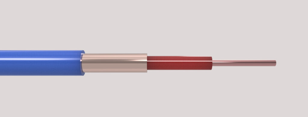
The conductor transmits the signal and can be made of a single copper wire. However, it is more common for the conductor to made up of multiple super-fine copper wires twisted together. The twisted configuration allows the conductor to be bent multiple times without snapping. A single larger diameter conductor is much more susceptible to metal fatigue. In either case the conductor is normally tin-coated to make the conductor solderable.
The dielectric has two functions. Firstly, it is to electrically isolate the conductor from the shield. Secondly the material is chosen to maintain consistent electrical properties and minimize signal loss. These are critical considerations when working at high frequencies as attenuation and signal reflections at the cable termination can cause significant issues in the performance of the equipment. The dielectric constant (also known as the relative permittivity of the material) controls how easily the dielectric can become polarised and is a key parameter in the cable design. There is a design challenge in achieving the required dielectric constant for the required dielectric thickness, whilst maintaining flexibility of the cable. One innovation is the use of foamed PTFE as a dielectric. The dielectric has microscopic voids within it which lowers the dielectric constant. Due to its fragility, it is often coated in an extruded or tape wrapped layer.
The function of the shield layer is to contain the electro-magnetic field generated by the high frequency signal. This can be to keep interference out, or to keep high power signals in. The shield is typically constructed with multiple strands wrapped around the dielectric in a spiral formation. This is known as a “served” shield. Served shields are much more flexible and compact than braided shields that might be found in larger coaxial cable designs. The shield wires are typically tin coated ultra-fine copper wires. Manufacturers are also starting to work with innovative shielding materials such as graphene to achieve the ultimate in size and flexibility, but this technology is currently in its infancy.
The served shield has to be contained by a polymer jacket, else it would bunch and unwrap. This jacket is a hard wearing, low friction polymer coating that binds the cable together and protects the inner layers. It does not significantly contribute to the electrical performance of the cable.
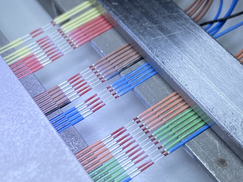
Micro-coax cables are typically terminated directly to a PCB or to a pluggable connector. In either case it is normal for the individual micro-coax cables to be laid side by side in a linear array, either in a single layer or on both sides of the PCB / connector. To aid with the connection it is common to “ribbonize” the cables. This means pre-placing the cables at a fixed, tight, pitch and joining them together. This makes alignment with the connector pads more manageable. Alternatively, features in the connector or a metallic jig can be used to fix the cable positions relative to the PCB or connector.
When it comes to connection to the PCB or connector, the norm is to use soldering. The cable conductor and shield are coated in a solderable tin layer and the receiving pad or connector pin have a small amount of solder applied to them. Heat is then applied to melt the solder between the cable layers and the PCB/connector. Depending on the connector / PCB construction the heat could be applied in the form of a “hot bar” solder unit or if the geometry is complex, the heat can be applied by a focused laser beam.
Stripping the cable: what does it mean and why is it a challenge?
Before the cable can be connected to the PCB or connector, it is necessary to individually expose the shield and conductor of the cable and align them with the mating connection on the PCB / connector. This process step is called the “cable stripping”. High frequency micro-coax cables have some of the most stringent stripping requirements, as there is a very small tolerance in the dimension of dielectric between the end of the shield and the exposed conductor. This dimension plays a critical part in the signal integrity. In addition, the delicate nature of the dielectric material and the very small dimensions of the cable elements create a perfect storm for the challenge of stripping the cable accurately and repeatably.
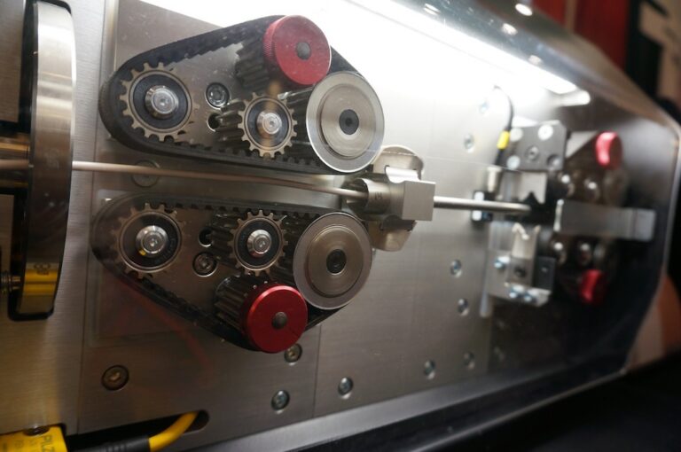
Mechanical stripping machines dedicated to the stripping of coaxial and micro-coaxial cable have developed over the last 40 years. State of the art units such as the Schleuniger 5300RX or Komax Cosmic range use precision, high speed rotary blades to cut and pull off the jacket, shield and dielectric layers in succession before cutting the conductor to length. Due to the small size and flexibility of the micro-coax cables the precision required is phenomenal as over stripping will critically damage the cable and under-stripping will lead to torn dielectrics or uncut strands which lead to catastrophic signal degradation. With careful set up and regular changing of the blades, micro-coax can be routinely stripped mechanically but there is a practical lower limit to the cable size that can be stripped. Typically for cable with an outer diameter much below 0.1” (0.25mm) mechanical stripping is not an option. In addition, as the mechanical units can only strip one cable at a time, using them causes challenges when having to connectorize large numbers of micro-coax in an array.
Laser Stripping: the solution
As with the case of laser soldering, lasers are sources of intense energy that can be focused to very small sizes and precisely controlled. This makes them excellent precision cutting tools. Unlike mechanical blades, laser stripping is non-contact and hence the process is consistent throughout the life of the equipment with no requirements for complex and frequent calibration or expensive consumable blades. More fundamentally, properties of the laser light can be carefully chosen to selectively cut one layer of material without damaging the underlying layer. This enables a good process window and removes the lower limit from the dimensions of the materials being stripped.
Laser stripping was pioneered in the 1980s for the NASA space shuttle program due to the requirement to minimize the thickness of wire insulations for weight considerations. Laser stripping has been routinely used in precision stripping of high value cables ever since. However, for complex cables such as micro-coax, it is necessary to deploy the latest advances in industrial laser technology and have a thorough understanding of the myriad of process parameters needed to achieve the required end result.
Typically, two distinct types of laser have to be deployed. One for stripping the polymer jacket and dielectric and the other for cutting the metallic shield.
Carbon dioxide lasers are relatively simple, mature industrial lasers. They emit light in the deep infra-red part of the electromagnetic spectrum. The first key property of this light is that it is strongly absorbed by all polymer materials, no matter the colour. Secondly, the light is almost totally reflected from any metallic layer. This means that when stripping off the jacket, the shield protects the inner dielectric layer from the laser light and when stripping the dielectric, the light reflects harmlessly off the conductor, no matter how small. The light is focused to a small spot of typically 0.1” (0.25mm) in diameter and is passed over the cable from at least 2 sides to form a 360-degree strip. The light heats the polymer causing it to melt or vaporize. A fume extraction filter, as used on a solder station, removes the fume from the process area and neutralises it. This stripping is a thermal process, but by controlling the amount of time the laser is hitting the cable, it is possible to cut and remove the polymer layers without overheating the inner layers of the cable.
There are two ways the laser can be used to remove the jacket and dielectric insulation. In the first, the laser makes a thin cut line akin to that of a mechanical blade. Once the layer is cut the insulation can be slid off the underlying layers to expose them. The advantage of this method is that the metallic layers that are exposed are totally clean as they are untouched by the laser. The challenge is that for some cable designs, the insulation layers are tightly adhered or even totally bonded. This can cause difficulties in removing the layer and can requires some lateral thinking in the mechanics needed to remove the cut insulation. Alternatively, the laser can be used to totally vaporise the layer of insulation revealing the shield or conductor. This has the advantage of being totally non-contact and easy to implement but careful laser parameter selection is needed to ensure residue is adequately removed and the inner dielectric is not overheated.
A totally different laser type is needed for cutting the served shield. It is important to select a laser that is strongly absorbed by the metal strands and yet not be strongly absorbed by the underlying dielectric. At first glance, it seems an impossible challenge to vaporise copper on top of a delicate plastic dielectric layer without damaging it. The key to unlocking the problem is to use a short wavelength pulsed laser. The carbon dioxide laser delivers its light in a continuous manner, in the same way switching on an LED torch would. The light interacts with the cable for as long as the focused spot is hitting it. A pulsed laser delivers similar amount of power as the carbon dioxide laser but in incredibly short pulses – typically no longer than 0.00000001 seconds (10 nanoseconds) long. These lasers have only been industrialised in the last 10 years and careful selection of the laser type and supplier is necessary to achieve the best results and the necessary equipment reliability. Each laser pulse is incredibly intense and is absorbed by the copper wire forming a small pool of melted copper which then immediately transitions into a gas. Heat is transmitted into the plastic relatively slowly, so as long as there is a pause between the pules, it never gets hot and melts. However, it is important that the dielectric largely reflects or at least scatters the light. If the material strongly absorbs the laser light, even though it is pulsed, it will create damage. This is a key point in the cable design. Dielectric insulations that are black are usually not possible to use with laser stripping as they are damaged during the shield cutting. White insulations are the best, showing no damage at all. Light colours generally work well, as do translucent dielectrics. The laser and optics delivery are designed to give a very small spot size (approximately 0.01” / 0.025mm). This ensures a sharp cut through the shield and minimizes the heat load on the dielectric. The small spot sizes means the laser focus has to be closely controlled to ensure the cable is at the point of maximum laser intensity.
The above pointers are a rule of thumb. With experience and control of dozens of process parameters it is usually possible to find a process that works, however the size of the process window does depend on the materials and construction selected. It is therefore very important to consult closely with a specialist laser supplier when designing new micro-coax cables or processing existing cables to ensure you are considering the laser absorption performance of the materials as well as the electrical signal performance.
Case Study
Ultra-sound cables utilize over a hundred micro-coax cables to transmit the data from the ultrasound head to the processing equipment in the hospital consulting room. A key challenge for cable designers is to make the long cable as light and as flexible as possible. This is because of increasing concern for repetitive strain injury (RSI) for the nurse who carries out this procedure multiple times a day. The cable manufacture’s requirement was to strip 128 microcoax in a single linear array and then solder those coax to a series of connector PCBs. The existing process was to use a mechanical micro-coax stripping unit – but the cable was just at the bottom end of the cable diameter specification. The Customer experienced a low yield per strip and extended stripper downtime due to the time needed to keep the mechanical stripping process in tolerance. As there is only so much length of cable to rework after an issue, it was resulting in high scrappage overall and low efficiency.
The full ultra-sound cable assembly contained the bundle of micro-coax cables in a protective outer jacket. To make the connection, the outer jacket and binding of the cable is removed manually with a blade to expose the inner micro-coax. A custom holding fixture was designed to hold the micro-coax in the linear array at the correct pitch. The fixture also tensioned the cables to ensure they are at a consistent height for the laser process. After consultation with the cable designers, the construction of the cable was fixed with a served shield, white expanded PTFE dielectric with a red protective wrapping and a 42 AWG inner multi-strand conductor.
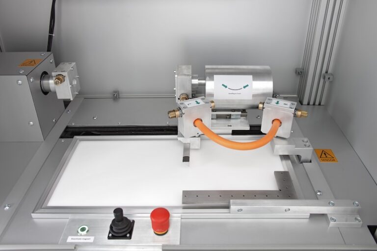
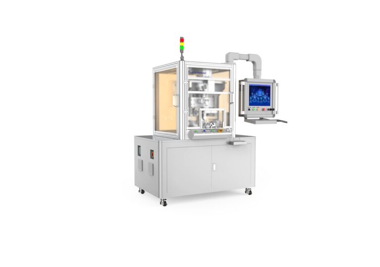
Separate carbon dioxide and pulsed laser modules are available on the market as standard units for performing these operations. A custom fixture can be designed to mate with the specific cable design. In the case of using separate modules, the Operator has to transfer the fixture between the modules after each process step.
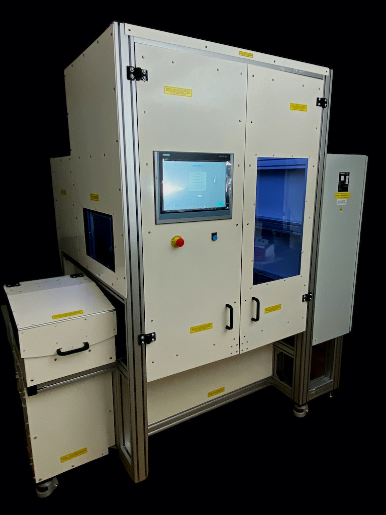
For this particular application, to minimize the cycle time and touch labour, the Laser Wire Solutions Micro-coax Centre (MCC) was recommended. The unit comprises of two laser units – one with carbon dioxide laser technology for stripping the jacket and dielectric and pulsed laser technology for cutting the shield. The fixture is transferred between the two stations automatically as the process requires multiple steps. The Operator loads the fixture which includes a clamp for firmly holding the body of the cable and the cable coil, and the guides for holding the individual micro-coax cables. The fixture is then moved under the carbon dioxide laser and the outer jacket is fully vaporised. The fixture is then moved to the pulsed laser module where the shield is cut in two places to create a window in the held micro-coax. A high-pressure air nozzle then removes the cut strands to expose the dielectric. The fixture then moves back to the carbon dioxide unit to have the dielectric vaporised as well. The whole process took under 4 minutes down from over 30 minutes for the previous process where the coax were stripped one by one and repeatedly reworked.
Summary
Micro-coax cables play an important role in the delivery of high frequency signals where the signal integrity and cable flexibility are critical, and the bulk of the cable is a constraint. New developments in micro-coax cable design is pushing the cable size below that which can be handled with state-of-the-art mechanical rotary strippers. Laser technology offers the perfect non-contact solution for stripping these complex, multi-layered cables. Laser stripping modules are available that can be used as standalone units for low volume manufacture or integrated into a semi-automated manufacturing cell where all the process steps are carried out automatically. The optimisation of the laser parameters to achieve the required precision results requires in depth process support from your laser partner. In most cases a laser process can be designed to give you the results you need. For the very best results, consult with your laser partner when selecting or designing your micro-coax cables to ensure the construction and materials used are optimised for laser stripping, not just the cable’s signal performance.