


Over the last 30 years since the founding of CAMI Research, customers and friends have asked why the company would focus its efforts on such a mundane, low-tech, and uninteresting device as a cable tester, particularly since a variety of such devices already existed. For the first year of our operation, I had nagging doubts myself for these very reasons, but, over time, these doubts have been spactacularly dispelled. On the surface, testing wiring assemblies might seem to be mundane. Instead, the incredible variety and richness of applications I will describe demonstrate that it is not. While a simple LED circuit can show continuity in a wire, the technology needed to meet increasingly complex and demanding customer quality standards is as different from an LED circuit as lightening is from a lightening bug. Whether something peaks someone’s interest, or not, is certainly subjective, however, even after 30 years, I find myself astonished at some of the applications customers bring to us.
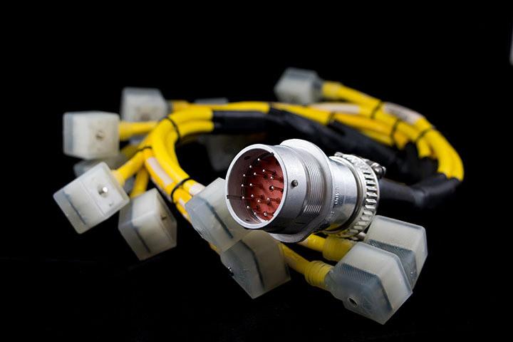
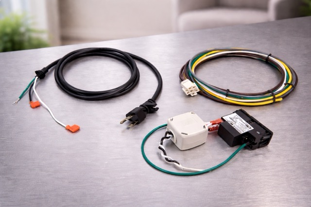
Note that in this article, “cable” refers to any wiring assembly from a simple lamp cord to a complex wire harness that might be found in an automobile or aircraft. The principles of testing do not change from one extreme to the other – it’s just a matter of scale.
The USB interface did not exist in 1993 when we begin work on the CableEye tester. At that time, computer peripherals including printers, scanners, modems, and industrial controls used serial ports to communicate with computers, a technology developed in the early 1960’s when teletype machines were in wide use. Initially, serial port cables used DB25 connectors and followed the RS232 standard developed by the Electronic Industries Association. For reasons of cost, competitive advantage, and advancing technology, very few manufacturers followed this standard exactly, and different, usually incompatible, serial cable wiring proliferated. Using a wrongly wired cable having DB25 connectors that obligingly fit most serial devices could cause device malfunction, or worse, circuit damage. With mass production came molded connectors now making it impossible to remove a cable’s backshell to see which color wire was connected to which pin. This left us with the mind-wretching task of using an ohmmeter or beeper to buzz out a cable to ascertain suspect wiring.
To address these problems, the company’s first goal was to develop a computer-based product to which a serial cable could be connected and its wiring instantly displayed on the computer screen. That succeeded, but it became quickly apparent that customers needed to test cables with many other connector styles, and required measurement capability beyond simple continuity to certify connection quality and search for various assembly defects like intermittent connections. Since the first CableEye tester was introduced, we have continually adapted to meet these ever-changing needs. The case studies that follow show some of the more unusual applications we have encountered over the years.
1 – Autonomous Underwater Vehicles are small, unmanned submarines that can operate without remote human intervention. Many companies make such devices of wide-ranging size for various purposes, including Woods-Hole Oceanographic Institute, Bluefin Robotics, and Boeing. Our customer, Hydroid in Pocasset, Massachusetts, makes deep-diving (up to 6000 m) vehicles for ocean exploration.
During the manufacture of these vehicles, various hull penetrations become necessary to admit wiring for external cameras, sonar, and electronic sensors. With the great pressure present at normal operating depth, water may seep through microscopic defects in wire insulation that would eventually lead the electronics to malfunction. As a result, all vehicles are tested in the factory using a large tank that can be pressurized to simulate the deep ocean. While under pressure, high voltage cable testing can reveal insulation defects that cause conductive liquid, like seawater, to intersperse copper conductors.
To test the quality of electrical insulation, we normally apply voltage between two unconnected wires and look for leakage between wires in fractions of a microamp. To obtain better than 1 GΩ of isolation between two wires, we would apply 1000 Vdc between the wires and expect to see leakage of less than 1 µA. The challenge in this application is that the water itself must serve as one of the conductors so that we can detect leakage under the insulation to a single wire rather than between two wires. However, the cable tester’s electronics require that all points be electrically isolated from earth ground so that each wire can be individually energized while other wires do not.
A body of water, unfortunately, is, of course, always at ground potential, including in a water tank attached to a grounded structure, so using the water itself as a test point becomes problematic. Since we could not electrically isolate the water in the tank, we instead isolated the tester and computer from ground by powering both through an isolation transformer, as shown in Figure 1. This permits successful measurements between the water and the wiring to confirm that the insulation remains intact.
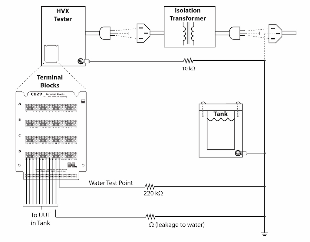
Figure 1. Test Set-Up for Submarine ROV.
2 – Medical catheters for electrical sensing or stimulation comprise small tubes containing extremely thin wires (fractions of a millimeter) that lead from an electrical connector at the near end to evenly separated electrodes along a short length of tube at the far end. Figure 2 shows an example.
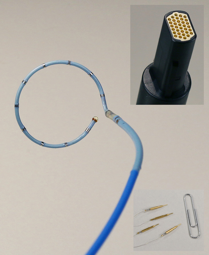
Figure 2. Medical Catheter.
Testing a completed assembly involved developing a special fixture to make physical contact with the electrodes without damaging them; simply clipping a minihook connector to each electrode would not only be awkward but could apply enough force to the electrode to deform it. The fixture we developed appears in Figure 3.
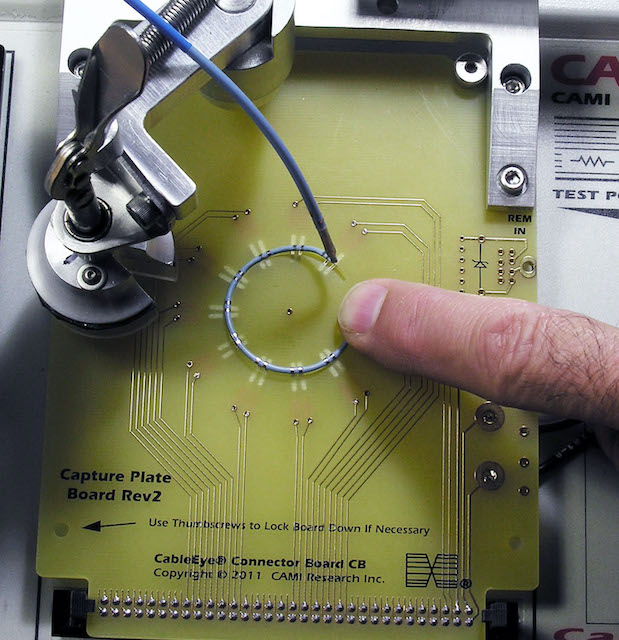
Figure 3. Medical Catheter, Connector, and Fine Wires to be Assembled and Tested.
We milled a circular groove in a 0.093” fiberglass circuit board to about half its depth. On the other side of the board, we milled slots perpendicular to the circular groove spaced at the positions of the catheter’s electrodes to just over half the depth of the board. This exposed openings along the circular groove where the electrodes would be located. By soldering-in a specially-designed spring pin on the back side of the board to terminate at each opening along the groove, we could make electrical contact with the catheter. A circular clamp closing from above applied uniform pressure around the catheter to ensure all electrodes touched the spring pins. Once mounted, a test with resistance could be completed in about one second. A report on the test result appears in Figure 4.
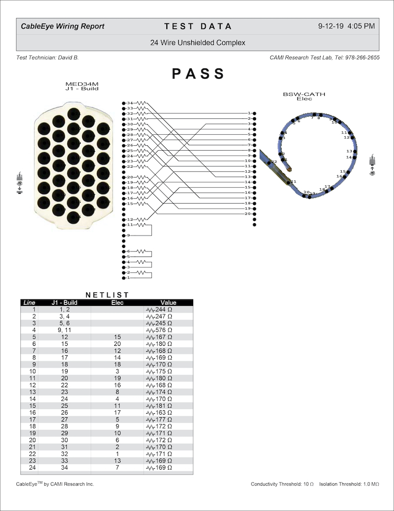
Figure 4. Catheter Test Report.
3 – Slip rings provide continuous electrical contact with rotating objects such as a constantly turning radar antenna. Newly manufactured slip rings require testing to ensure that low electrical resistance exists uniformly for the full 360° circle of rotation. Any discontinuities in electrical resistance could cause serious equipment malfunction, or arcing if the rings transmit power. Also, because some element of friction exists at the contact point between rotor and stator, periodic testing becomes necessary for equipment taken out of service for maintenance. Figure 5 illustrates how slip rings work, and Figure 6 shows how a cable tester connects to slip rings to make measurements, and the expected resistance samples that constitute Pass and Fail results.
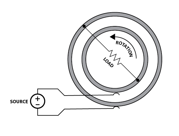
Figure 5. Slip Ring Schematic.
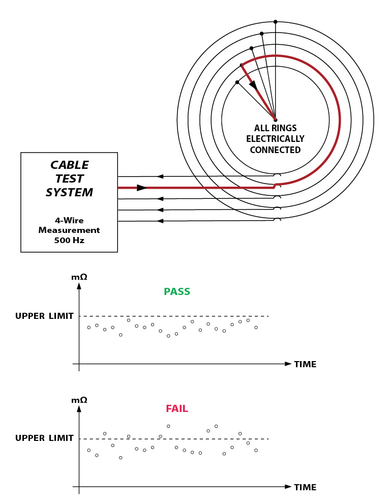
Figure 6. Test Set-Up and Results for Slip Rings.
For this application, we modified the tester’s firmware to make repetitive 4-wire Kelvin resistance measurements at the rate of 500 per second. Because the sampling process is not synchronized with the rotation, several rotation cycles will ensure that we collect enough resistance samples around the circumference to provide a high degree of confidence that the rings transmit electrical signals reliably through their full span of rotation.
4 – Crash test dummies substitute for human subjects when automotive manufacturers intentionally stage collisions to test vehicle safety systems. Unlike humans, these anthropomorphic creations contain numerous embedded sensors including accelerometers, load sensors, strain gauges, temperature sensors, angular rate sensors, air pressure sensors, and position sensors located where body stress and injury are most likely. Not surprisingly, these many sensors link to data acquisition modules using cables exposed to the same forces experienced by the various sensors. Following a crash experiment, these cables must be carefully inspected and electrically tested before reuse, especially considering the expense of a destroyed test vehicle and the possible loss of data from a failed cable.
5 – Extremely long cables connect computers, sensors, and other equipment separated by distances of thousands of feet or more, sometimes by miles. Simply connecting long cables to a modern cable test instrument without making some adjustments to the measurement process will produce spurious data. As wires increase in length, each wire begins to look more like the plates of an elongated capacitor, particularly when a shield conductor exists, as shown in Figure 7.
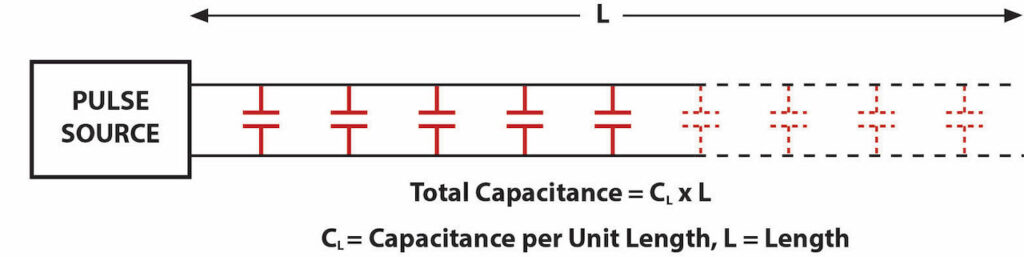
Fig 7: Visualization of Cable Capacitance.
Automatic cable testers, unlike ohmmeters, use a series of rapid pulses to acquire connection and resistance data, and unfortunately the parasitic capacitance of a long cable distorts these pulses. For connectivity and resistance measurements, generally widening the test pulses addresses the problem by permitting the tester’s drive circuit more time to pump charge into the parasitic capacitance before reading back a response. This also results in lengthening the test time. As with the autonomous submarine testing cited at the beginning of this article, the cable must be isolated from earth ground, or if this is not possible, the tester and computer must be.
High voltage testing of long cables presents us with the same capacitance issue, but in this case, the inrush current needed to bring the cable up to the test voltage may exceed the current level that would normally signify insulation breakdown (the “trip current”). In this case, we reduce the ramp rate to gradually increase the test voltage. Refer to Figure 8.
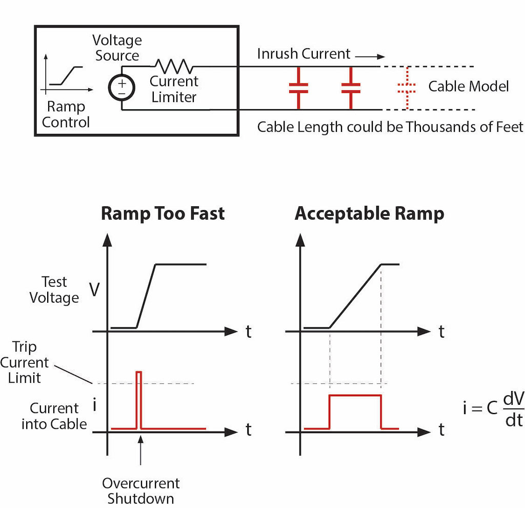
Figure 8. Test Set-Up for Long Cables – To reach the test voltage without first hitting the trip current, care must be taken to adjust the voltage ramp in accordance with the length of the cable.
Testing long cables with high voltage also introduces a serious safety concern. Unlike the low voltage test for continuity and resistance that uses 10 Vdc pulses, a hipot test may apply 500 Vdc or more to the cable to test insulation properties and leakage. We can certainly reduce the ramp rate while raising the voltage from 0 V to the test voltage, however, as we do so, we pump considerable charge in the cable owing to its large capacitance. If, for any reason, a person should come into contact with the far end of a long cable during the hipot test, they could receive a lethal electrical shock from the cable’s stored charge discharging through their body, so this demands special care on the part of those operators performing the test.
Conclusion
When development of the CableEye tester started in 1991, I expected the project to be completed in about one year, and once released, planned to turn production over to a contract manufacturer freeing me to work on another new project. It did not turn out that way. Instead, two years were required to bring the first model to market instead of one, and then, while many news releases resulted in much positive feedback, customers demanded more connector interfaces, more test points, greater measurement capability, and software that could print reports, log data, and provide guided assembly. Simply showing the wiring schematic of serial cables on the screen addressed much of the frustration in learning why an errant cable that fit a computer and its peripheral did not work, but that alone was not enough for a successful product. We needed a universal tester for cables, wire harnesses, equipment cabinets, and, in short, anything containing wires. While disappointed that I could not move on to a new project, the disappointment did not last. The incredibly diverse applications that revealed themselves in the ensuing years, some of which I’ve described in this article, allowed the original product to evolve into a flexible quality control instrument and provided interesting and rewarding careers for myself and my employees. Several times a year, new previously unknown applications appear to drive continuous, new development in CableEye’s software and hardware, and the product continues to evolve.