


HV Cable Terminations – Process Steps and Acceptance Criteria Made Easy
by Pete Doyon, Schleuniger, Inc.
For those who aren’t experts in high-voltage applications, I’d like to explain the key process steps and acceptance criteria in simple terms. There is no question that hybrid electric vehicles (HEV) and fully electric vehicles (EV) are here to stay. These types of vehicles use special cable to connect the battery pack to the electric drives, charging circuits and electric motor(s). This special type of cable is known as high-voltage or “HV” cable. It is typically orange in color, has multiple layers of insulation and shielding, and has one or more inner conductors. Since HV cables carry voltages up to 600 volts or more and high peak currents, each process step used to prepare the cable end for termination is critical to achieve the required performance of the cable assembly over the life of the vehicle.
Regardless of the type of tool or automated equipment that is used to process HV cables, the requirements are the same. Following is a step-by-step description of the individual process steps required to prepare and terminate a typical HV cable as well as the acceptance criteria.
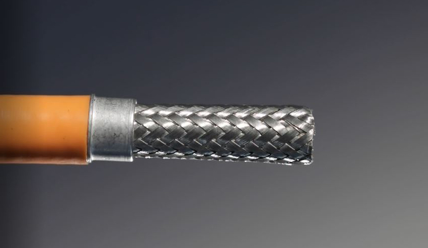
- Outer jacket stripping (Fig. 1)
The first step is to strip the outer insulation jacket to the specified strip length while ensuring that the underlying shielding is not damaged. The outer jacket is typically made of silicone, which is soft and slippery, making it difficult to strip. Sometimes the outer jacket wall thickness is not uniform along the entire cable length, making it even more difficult to strip properly. The cable must be inspected after stripping to ensure there is no damage to the underlying cable layers.
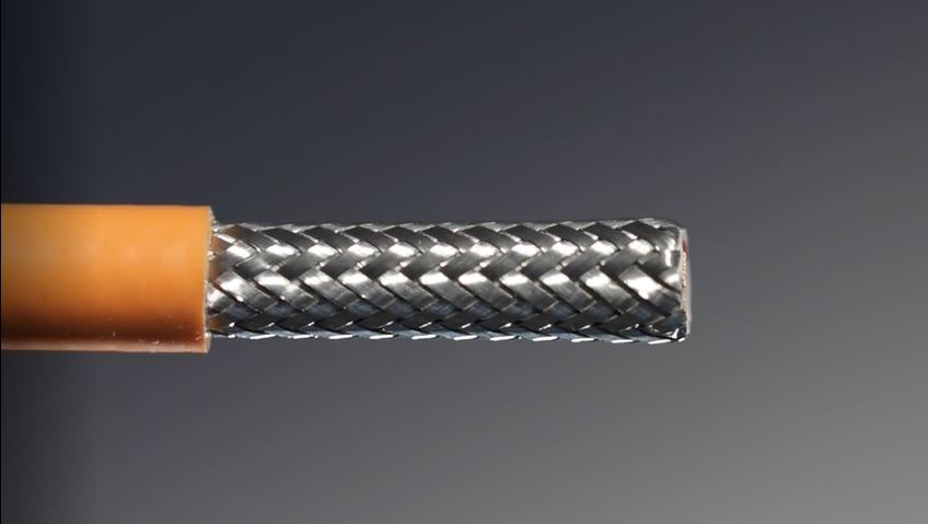
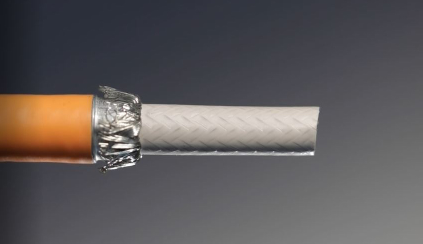
- Foil cutting (Fig. 2)
Some HV cables have a thin layer of foil bonded to a polyester backing. This foil layer must be cut cleanly and removed completely before the next processing step. Reworking or cutting with scissors is not acceptable. When cutting and removing the foil, the underlying braided shield must not be damaged in any way.
- Assembling the inner ferrule (Fig 3)
Inner ferrules come in a wide variety of shapes and sizes, making it difficult to automate this process step. The ferrule must be placed in the proper position on the cable without damaging the braided shield.

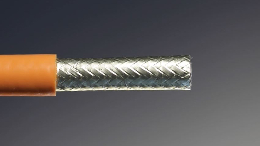
- Shield cutting(Fig. 4)
Due to the high risk of damaging the underlying cable layers, cutting the braided shield is one of the most difficult steps in processing shielded HV cables. The braided shield must be cut cleanly and squarely at the proper length with no uncut strands. All cut strands must be collected properly to prevent any possibility of a short circuit in the cable assembly or anywhere else in the vehicle.
- Shield folding (Fig. 5)
The shield is folded over the ferrule. The individual strands must be distributed evenly around the periphery of the cable or it could lead to faulty crimps during the ferrule crimping step.

- Cutting filler or dielectric (Fig. 6)
This layer must be stripped at the correct strip length position without any damage to the underlying cable layers. The main challenge with this process step is that the thin filler or dielectric insulation is not always uniform in thickness. Precise control over the cutting depth and a novel approach to slug removal are required to reach the required quality level.
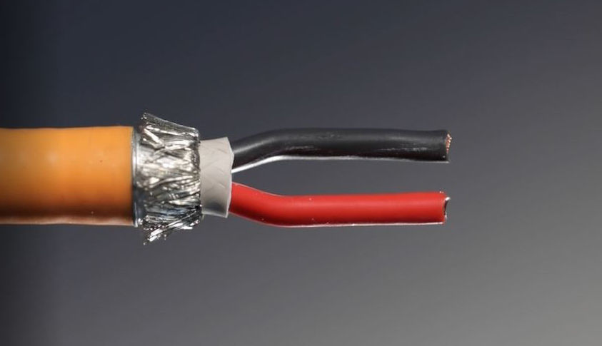
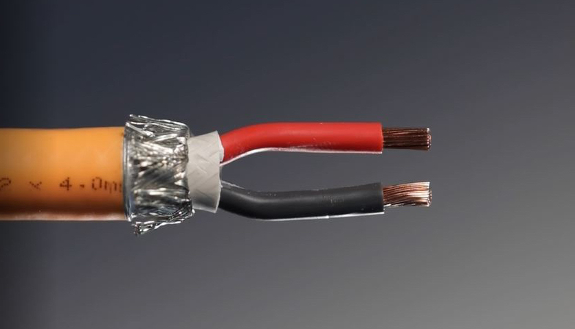
- Inner conductor orientation (Fig 7)
The inner conductor polarity is extremely important when assembling high-voltage connectors. Errors in polarity will not only prevent proper product function, they also present a safety hazard. Automation systems can orient the wires properly and form them in preparation for the next processing step.
- Stripping inner conductors (Fig. 8)
Another critical processing step is stripping the insulation from the inner conductors. The requirement is for strip lengths with very tight tolerances and no cut or pulled strands.
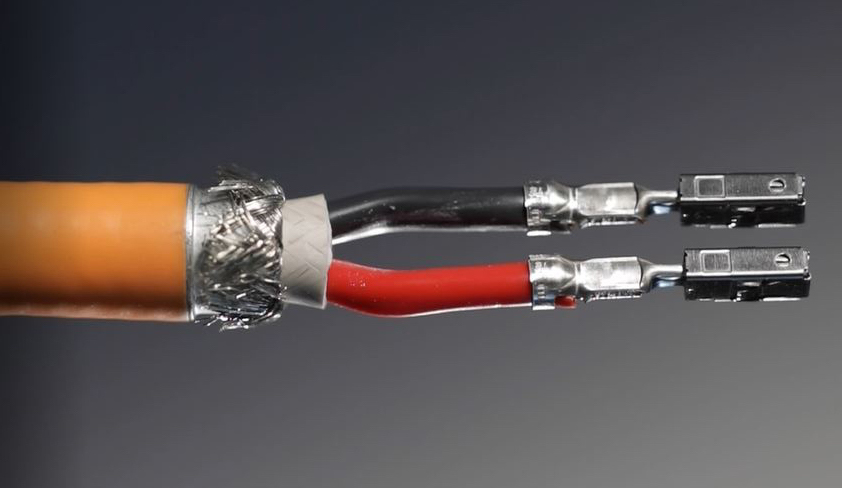
- Crimping inner conductors (Fig. 9)
Multiconductor crimping requires precise positioning of each individual wire before and during the crimping process. Automation systems have integrated crimp-force monitoring to verify that the crimp force is within the tolerance value that has been predetermined for a good crimp.
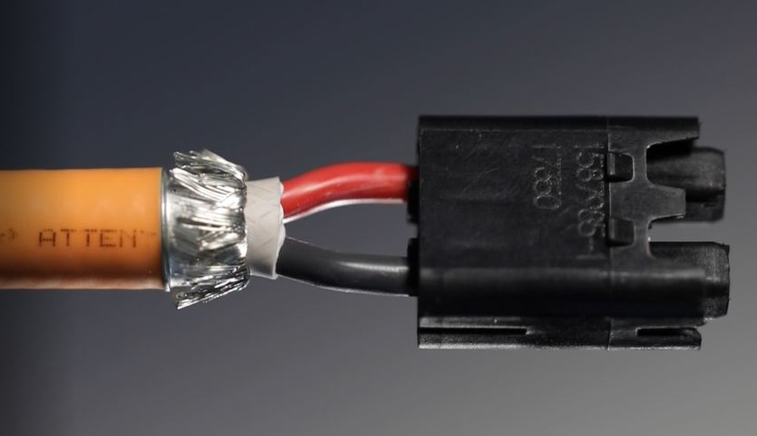
- Connector housing insertion (Fig. 10)
Plugging is one of the most difficult processes for high-voltage cable assemblies. Stiff cables, large cross sections and limited space increase the risk of damaging the crimped terminals during the plugging process.
If any of the process steps do not meet the acceptance criteria, the cable end cannot be used. More often than not, the cable end cannot be reworked, leading to production scrap. With the relatively high cost of HV cable, as well as the floor space and labor required for rework, production scrap is always an important issue.
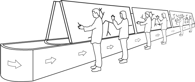
The key to higher first-pass yields is automation of all of the process steps. Automation systems reduce operator-induced variation, making it possible to achieve a stable process. Automation systems typically feature in-process quality monitoring to ensure that each step has been performed properly. While it is possible to use manual production processes to produce HV cable assemblies, increased automation will lead to higher quality and lower overall production costs.
Schleuniger is an international manufacturer of high-precision cable processing machines including state-of-the-art automatic and semi-automatic equipment designed to cut, strip, seal, crimp and mark all types of wire and cable. For more information, visit us at www.schleuniger.com.