


History of Connectors and Termination Tooling
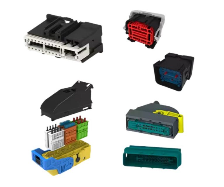
Since the beginning of flight and early propulsion systems, electrical conductors have been used to transmit a signal throughout the aircraft. As air travel evolved, so did the requirements for wire harnesses and connectors used in these systems. Today, Electrical Wiring Interconnect Systems (EWIS) are very complex incorporating both traditional power and high speed data signal. This complexity in wiring requires connectors, contacts, wire, fiber optics, and other technology that require precision tooling.
CRIMPING: THEN AND NOW
The first multi-pin connectors were terminated by soldering the conductor to non-removable contacts. However, high temperature applications and the need for simple and reliable field service led to the introduction of connectors with removable contacts. These were crimped onto the conductor rather than being soldered.
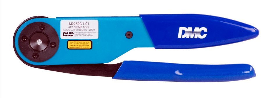
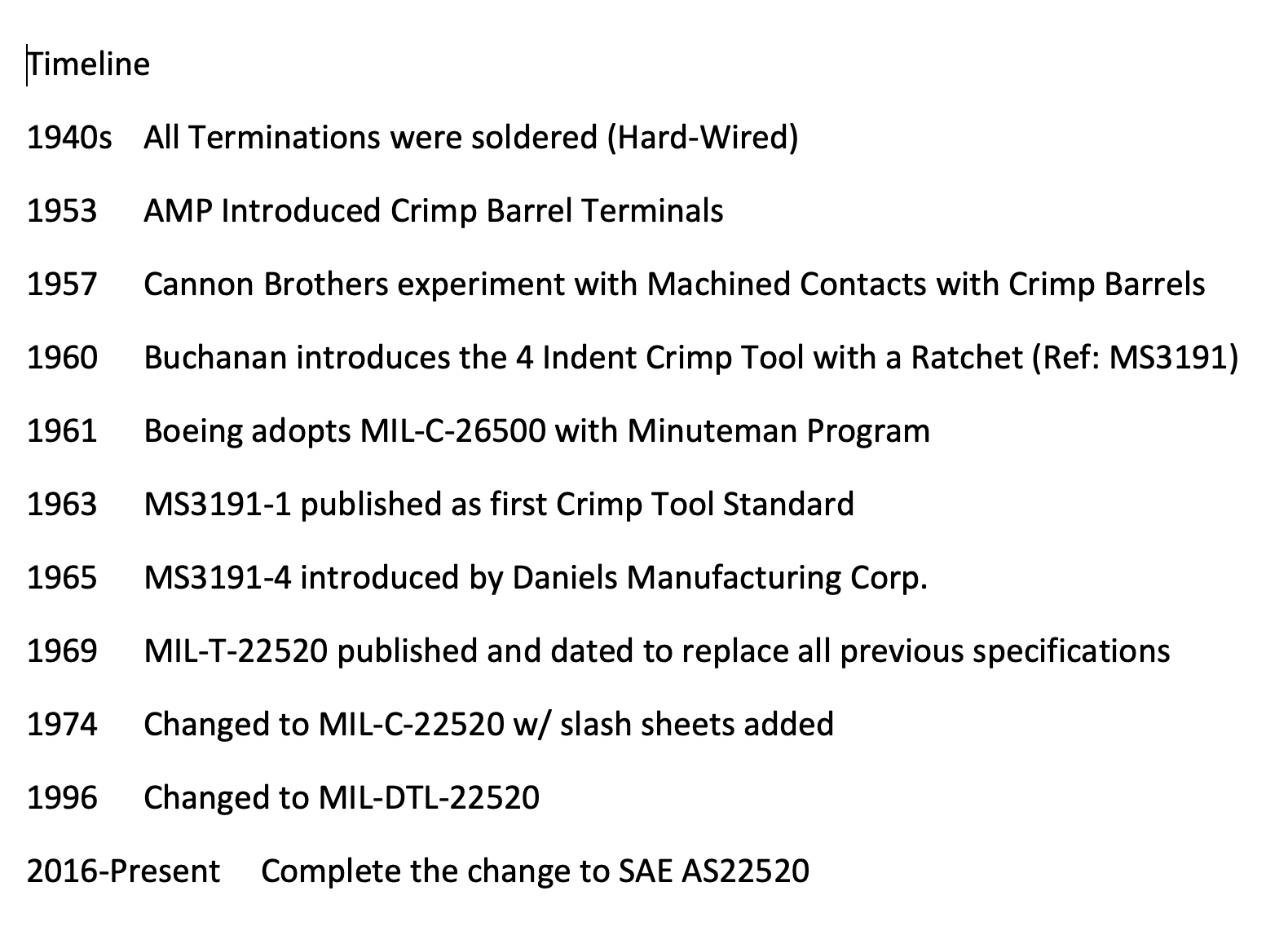
The first standard crimp tool developed to crimp these new contacts was introduced in the early sixties. MS3191-1, a military drawing, defined this tool and its accessories.
The MS3191-1 utilized a four-indent crimp pattern together with a positive stop locator which controlled the travel of the indenters (crimp depth).
The MS3191-1 design was a compromise between simplicity of operation and crimp performance since the crimp depth for any given contact was not adjustable to accommodate the differing diameters of the conductors to which it would be crimped. It was, however, suitable for the crimp connectors of that era. An improved tool design featuring independently adjustable crimp depths was soon introduced as MS3191-4.
The MS3191-4 had an internal adjustment, totally independent of the locator, which permitted the selection of seven separate crimp depths, allowing optimal crimping of conductors ranging from AWG 12 to 26 regardless of the wire barrel size of the contact. MS3191-4 also introduced the use of the double tipped indenter to produce an eight-indent crimp pattern which has consistently achieved superior tensile pull off values and mechanical properties.
MS3191-4 introduced the concept of a turret head containing three locators which could be used without separating any of them from the basic crimp tool.
In 1969 two military specifications for crimp tools were developed to replace the existing military drawings. They were MIL-T-22520C (Navy) and MIL-T-83724 (USAF) which defined a standard size crimp tool similar to the MS3191-4, but with an expanded eight step crimp depth range. These specifications also defined a miniature crimp tool to crimp conductors as small as AWG 32. Both documents were combined in 1971 into MIL-C-22520D. All previous military standards for crimp tools were then cancelled including the MS3191. This list includes specifications for indent crimp tools, terminal lug crimp tools, pneumatic tools, coaxial cable crimp tools and other specialized crimp tools.
MIL-DTL-22520 established a single specification which set forth performance requirements for all crimp tools to be used on military standard electrical connectors. This eliminated the waste and confusion which accompanied the overlapping applications of many different “standard” crimp tools called out by a deluge of unrelated military drawings.
THE CRIMPING CONCEPT
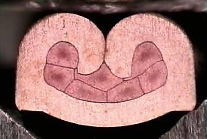
Crimping is a method of firmly attaching a terminal or contact end to an electrical conductor by pressure forming or reshaping a metal barrel together with the conductor. The forming of a satisfactory crimp depends on the correct combination of conductor, crimp barrel and tool. When applied with a properly matched tool, a union is established which has both good electrical and mechanical characteristics. The tool will provide these requirements consistently and reliably with repeatability assured by quality cycle controlled tooling.
There are several common configurations of crimped joint; several examples are shown below.

The electrical resistance of a properly designed and controlled crimped joint should be equal to, or less than, the resistance of an equal section of wire. Specifications state the requirements in terms of millivolt drop at a designated current.
The mechanical strength of a crimped joint and hence its pull-out force (tensile strength), varies with the deformation applied (i.e. the crimp die of the tool determines the crimp configuration and deformation). Therefore, by properly shaping the deformation, a high pull-out force can be achieved. The dies in the tool determine the completed crimp configuration which is generally an element of contact and/ or connector design.
Some of the design considerations are: a) The type of contact, its size, shape, material and function, b) The type and size of wires to be accommodated, c) The type of tooling into which the configuration must be built.