


EWIS:
EMI and DO-160
By Michael Traskos
Designing a circuit diagram for a system comprised of Line Replaceable Units (LRUs) is usually a straightforward process: identify the inputs and outputs of the system and connect them with wires and cables. Taking that simple high-level circuit diagram and implementing the physical design into an application can be quite difficult. This requires the proper connectors, OPTIMIZED THE PHYSICAL ROUTING, and ensuring negligible impact from electromagnetic interference (EMI). From an implementation perspective, it cannot be understated how much EMI can IMPACT SYSTEM PERFORMANCE ranging from degraded performance to make a system completely inoperable. Thankfully, there are test methods to evaluate the susceptibility of electromagnetic interference of a wire harness design.
In this article, we will review some of the test methodologies outlined in RTCA D0-160 for the performance of EWIS harnesses and the susceptibility to electromagnetic interference. We will talk about the three areas that directly focus on interconnecting cables which include magnetic fields, electric fields, and electrical spikes.
THE SPECIFIC CONFIGURATION
As a starting point, it is important to know that the tests outlined in the DO-160 are for the specific case and require some work to be considered for the generalize case. The testing, as it is outlined in the standard, specifically is focused for the application and the validation of interconnecting cables for a single system. Often with these tests, two system components are separated by interconnecting cable and the interference is injected into that wiring harness.
Ideally, the equipment and cables should be installed such that they match the installed configuration. Further, any signals or power running between the equipment should be properly simulated during these tests. This would then allow for an evaluation of what can happen to the signals as the interference is injected.
MAGNETIC FIELD
For the consideration of magnetic field interference, the representative system is laid out and a current carrying loop is aligned with the wiring harness. This is done to generate a magnetic field and create mutual inductance between the current carrying loop and the wire harness under test.
Depending upon the application and the power available in the representative aircraft, different power system configurations and voltages are to be used. As each of these creates a different magnetic field the specific impact to the system needs to be evaluated. While it may not be installed along power wires during the initial installation, subsequent modifications to the aircraft may create a scenario in which power wires from other systems may be placed in close proximity. To avoid future problems, the susceptibility of the system to a magnetic field should be evaluated.
ELECTRIC FIELD
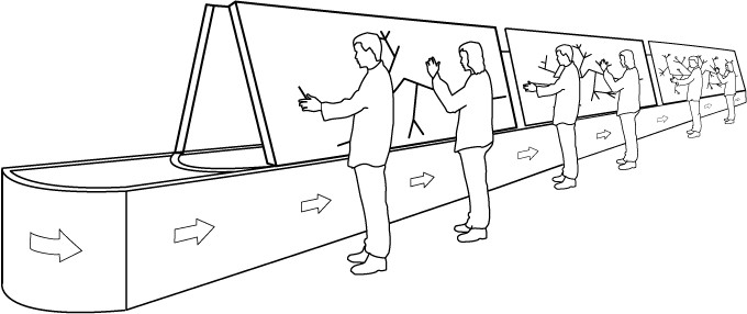
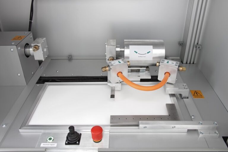
The injection of an electric field into the wire harness under test is a little more involved than the magnetic field set up. In this test, the circuit wire is wrapped helically around the wire harness in a specified manner. Unlike the magnetic field tests, the electric field system does not have a closed circuit but rather is attached to a signal generator and the voltmeter to measure the generated signal.
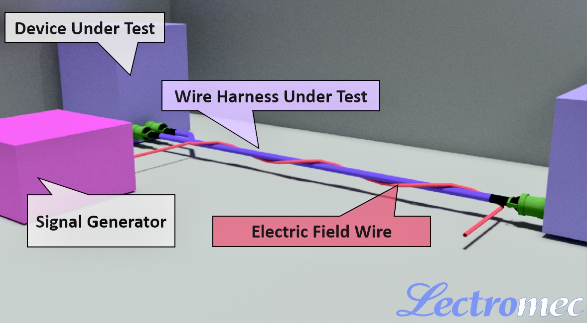
(Setup for the electric field test per DO-160. The induced electric field wire will carry 170V RMS at 400Hz.)
The interesting element of the electric field test outlined in DO-160 is that the only voltage/frequency configuration considered in the testing is that of a 170 V RMS and 400 Hz power system. One would suspect that in applications that has higher voltages, particularly AC voltages, would augment this test in order to accommodate for it.
INDUCED SPIKES
Induced spikes are probably one of the more difficult elements to detect in in-service applications. As these transients are short-lived and created by other systems with collocated wiring, it can be difficult to identify the source of the problem when occurring in an installed application. To replicate this test scenario, the wire harness under test is set up similar to the harness described in the electric field set up. One change with this test is that, rather than having an AC voltage and power applied to the system, the system is attached to a 28 voltage DC power supply rapidly activating and deactivating an unsuppressed coil relay. Those familiar with surges and back EMF generated by a relay activation are likely also aware of the impact an unsuppressed coil relay can have on circuitry.
In this test, the relay is rapidly activated/deactivated and the effect on the wire harness under test and system is evaluated as it would be with the other two aforementioned tests.
CLOSING REMARKS
RTCA D0-160 provides a means to evaluate the susceptibility of system wiring to electromagnetic interference. Specifically, these tests evaluate the electromagnetic fields and impacts that could be experienced in a real application. Naturally, these tests specifically evaluate the induced signal susceptibility of the wiring harness and to the subsequent connected equipment.
However, these tests alone do not cover all considerations for EMI protection of the wiring harness or system. Other factors such as radiated fields, cross talk, and a whole host of other EMI sources should be considered before fielding the system. As one might suspect, selecting a quality cable with proper shielding and design can go a long way to protect an aircraft’s EWIS from electromagnetic interference.
To find out more about how to evaluate your wires, cables or system wiring harnesses, CONTACT LECTROMEC. Our team is ready to help.
About Michael Traskos:
Michael is President of Lectromec and has been involved in wire degradation and failure assessments for more than a decade. He has worked on dozens of projects assessing the reliability and qualification of EWIS components. Michael is an FAA DER with a delegated authority covering EWIS certification and the chairman of the SAE AE-8A EWIS installation committee. Contact Michael at [email protected]