


Improving Cable Quality & Reliability
Electrically Checking Crimps with Multiconductor Testers
Overview
Crimped connections may be defective mechanically and/or electrically. Multiconductor testers are powerful tools used for qualifying electrical integrity. Delivering empirical data, they can provide full measurement data for every pin-to-pin connection. Here we discuss the best practical way to test for electrically bad crimps.
Crimps with a mechanical defect resulting from insufficient pressure during the closure process can be detected with a crimp-pull tester – this is a mechanical device that applies controlled physical separation pressure to the crimp confirm that it is adequately tight. Crimp Force Monitors (CFMs) can detect missing strands, crimp-caught insulation, and more. Such crimp testers do not directly check actual electrical integrity.
Today, most companies manufacturing and/or integrating cables and wire harnesses, will test electrical integrity with programmable, automatic multiconductor testers – time-saving, productivity-boosting equipment that checks for and locates faults across all conductors of the Unit Under Test (UUT) without operator intervention.
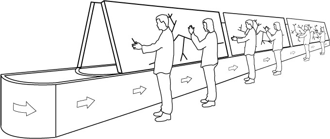
The best practical way to test for electrically bad crimps is to first perform a standard continuity and resistance check (Fig. 1), followed by an intermittent connections test where signals are constantly sent through the cable while you flex the connectors and apply stress (including pull) to the cable itself (Fig. 2).
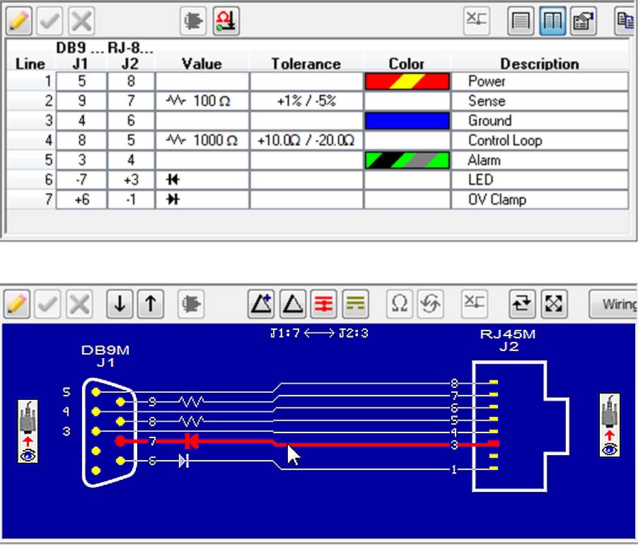
Figure 1. Netlist and Graphic Test Display

Figure 2. Intermittent Fault Check
A stray wire strand, for example, may cause an intermittent short to a neighboring pin, crimp-caught insulation may cause intermittent changes in line resistance, and a wire with enough cut strands will simply fail the resistance check.
The Production Manager or Production Engineer will have previously programmed the tester with well thought out UUT-specific pass/fail electrical parameters including tolerances. To optimize yield, advanced testers allow tolerance settings in absolute or percentage terms as well as asymmetrically (e.g. +1% -3%) – see Fig. 1.
If all of these tests pass, then any unfound severed or stray strands or partial-crimp-over-insulation on a wire will be safe to use in practice. In other words, for electrical performance, it is not essential to ascertain how many strands (if any) have been cut in the stripping process, or if insulation has been caught in the crimp, only whether the final crimp passes the required electrical continuity, resistance, and intermittence tests. Professional multiconductor cable testers can perform all of these tests.
Too often, checking for intermittent faults is omitted either from the Work Instructions or from the performance of the Work Instructions, so take an impromptu visit to the electrical testing work stations to note whether testing for intermittence is being done.
Sensitive, Accurate, and Precise Resistance Measurement
Four-Wire Kelvin measurement (Fig. 3) with multiconductor testers makes it possible to accurately and precisely measure resistance values less than 0.1 ½ while eliminating the inherent resistance of the lead wires connecting the measurement instrument to the component being measured. In some cases, your resistance check should be carried out with this technique.
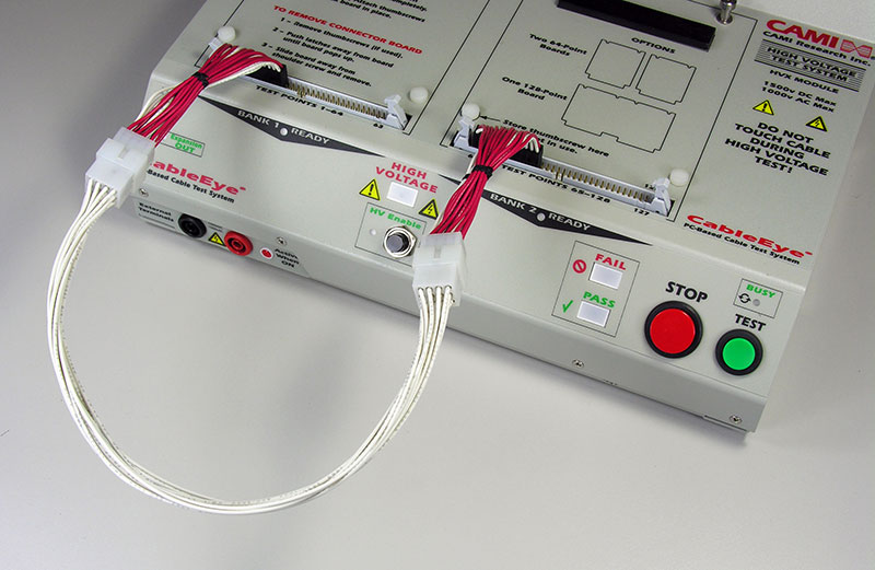
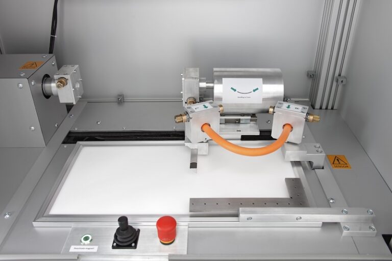
Figure 3. UUT Attached to a CableEye test system
Side note: Figure3 shows a UUT (all-white cable) attached to a CableEye® test system via two 4 Wire test fixtures (red/white cables). The 4-wire test system requires twice as many test points as a standard two-wire resistance test. Consequently, the test fixture requires two wires [one Source (red) plus one Sense (white)] for every pin on the UUT. You can see that 48 test points are required to test this12-conductor cable.
Precise and accurate low-value resistance measurements become necessary when testing cables intended to carry significant current, or when extremely high reliability must be ensured in medical or military applications. For cables intended to transmit power as you might find in AC power distribution or radio transmitters, low-resistance connections that have faulted to high-resistance create the real danger of fire or explosion.
Although cables used in some high reliability applications do not carry significant current, questionable connections to hair-thin wires connecting a monitor to high-precision sensors could create life-critical measurement error or circuit misoperation.
Cut (or Missing) Strands
It is a common misconception that the more sensitive 4-wire resistance measurement technique will easily detect a single cut or missing strand of wire when applied by a multiconductor tester. Typically, in fact, the electrical performance of a cable due to a cut (or missing) strand is not sufficiently degraded to be measurable. Several affected strands, however, might be detectable as an out of tolerance resistance measurement as shown next.
This demonstration of 4-wire measurement sensitivity begins with a 3.5” (8.9 cm) length of 22-gauge 7-strand wire, UL07730 connected between two screw terminals. The UUT runs between Source test points 49 and 55, with corresponding Sense test points 50 and 56 appropriately linked, as shown in (Fig. 4). The system is programmed for a 1A test current.

Figure 4. Experimental set-up with 7 intact strands
The strands will be cut, one-by-one, with resistor measurements made at each step, to determine how the resistance varies with the number of intact strands. Figure 5 shows three cut strands with four strands remaining.
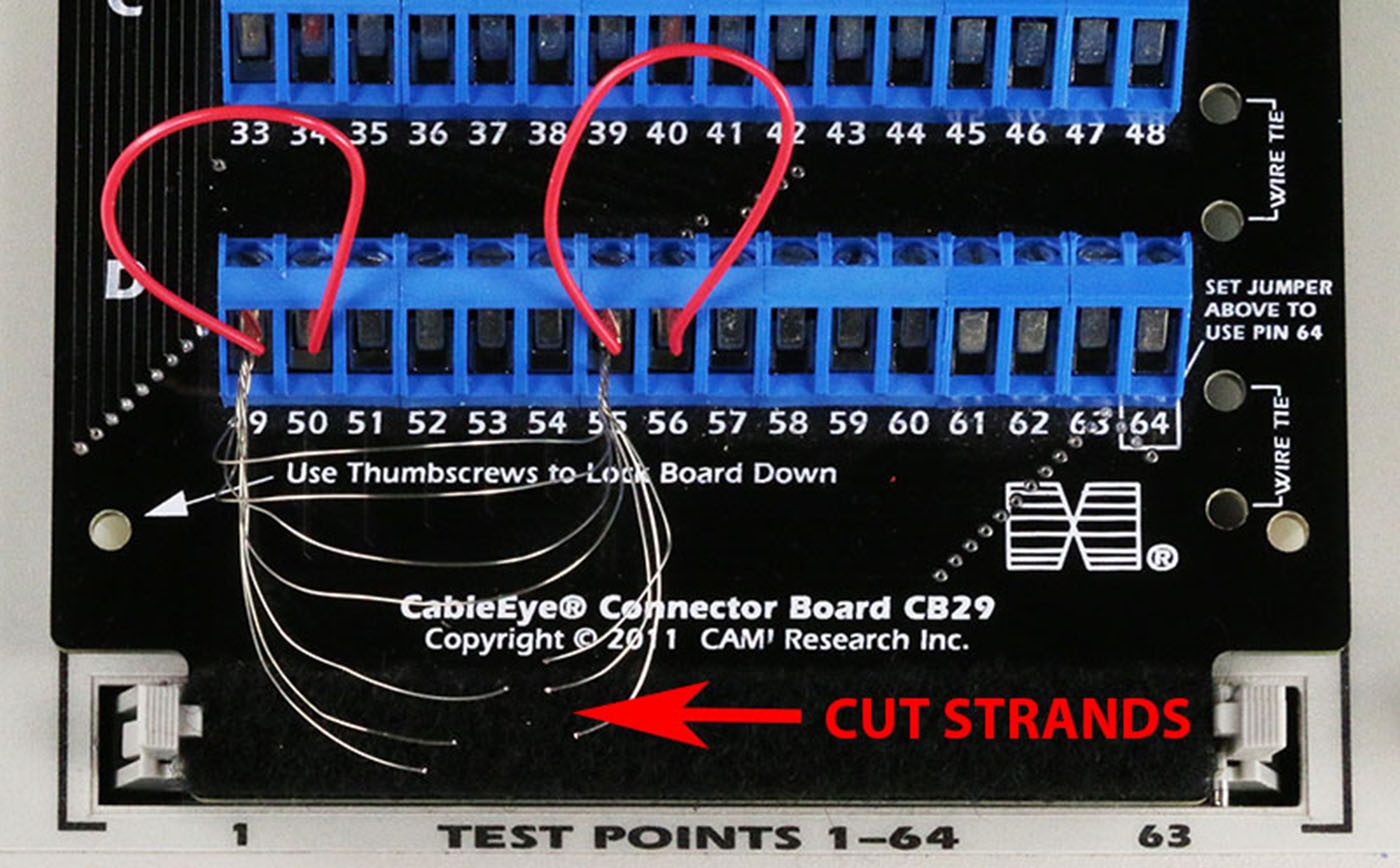
Figure 5. Experimental set-up with 4 intact strands
Here (Fig. 6) you see the screen report from the CableEye tester with all but two strands cut.
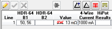
Figure 6. CableEye screen report of 4 wire test
Table 1 summarizes how the resistance changes as strands are cut, and as a function of dwell time. Interestingly, with only one strand remaining to carry the 1ÊA test current, no heating was detectable by human touch, although clearly the resistance increased slightly with the current applied for 1 second or longer compared to the initial short 50 ms dwell.
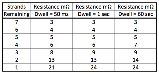
Table 1. Experimental results – Change in resistance as strands are cut
The most flexible testers allow Users to set different test currents and dwell times for different conductors within the same UUT, and for this matrix of conditions to be tested ‘simultaneously’ on initiating the test. This flexibility is especially necessary when the UUT contains an array of signal and power conductors.
Even a 4-wire test sensitive to a milliohm and passing 1 A of current continuously through the cable cannot pick up a defective crimp where the crimp is tight and the defect is crimp-caught insulation.
Summary
Application of 4-wire Kelvin measurement techniques will improve the quality and reliability of your cable and harness products. Multiconductor testers with 4-wire capability are typically limited to a sensitivity of 1 m Ω. Precision resistance measurements of less than 0.1Ωreveal wiring defects not visible to less sensitive measurements, including bad solder joints, and pin contact contamination. Resistive losses resulting from these defects in applications carrying current above 1Amay cause excessive heat generation or fire in wiring, or in the case of measurement circuits which obtain input from precision sensors, may cause false reporting or circuit misoperation. The 4-wire Kelvin resistance method not only makes it possible to obtain milliohm-sensitive measurements precisely, but also eliminates any effect of incidental resistance that would be introduced by test leads or the test fixture.
While this is a more sensitive measurement technique than standard two wire resistance testing, it still lacks the sensitivity to diagnose single-cut strands, single-stray strands, or crimp-caught insulation. However, combining continuity, resistance, and intermittence testing with use of appropriate test settings (wire resistance values, tolerances, dwell times etc.) provides confidence of the electrical integrity of the part backed with direct empirical evidence.