


Capital Formboard Manager:Technology for Greater Wire Harness Manufacturing Efficiency

By: Frank Hemmersbach
To optimize production lines, wire harness manufacturers sometimes build different but very similar harnesses on the same “merged” formboard, a method allowing for efficient use of both factory space and production line resources. This article first explains the existing challenges with this production line optimization method, then it describes and how the Mentor Graphics’ Capital tool suite supports engineering teams in overcoming these challenges to more quickly reach the zone of manufacturing profitability.
Introduction
The wire harness industry is very competitive. Increasing complexity is straining profitability of the manufacturing process, which is still highly manual and labor-intensive. This situation will almost certainly continue into the foreseeable future given megatrends such as electric vehicles and autonomous driving and their associated impacts on electrical distribution systems. In addition, harness makers still have to manage and implement lots of design changes even while the product is already in production, further impacting production lines. Resources like operators, equipment and even factory space are very valuable and must be managed with care.
The initial setup of a production line is itself a major endeavor requiring much manufacturing engineering experience. Preparation areas must be designed, harnesses must be arranged on formboards, holes for supporting fixtures must be drilled, supporting fixtures must be mounted to the formboard, workstations must be defined and content needs to be assigned to these workstations. Test equipment also must be designed and prepared. The whole production line must be balanced based on the given takt-time and forecasted take rates. Decisions must be made, based on the forecasted volumes, as to the required number of production lines and factory space. All of this happens with the goal of moving as soon as possible to profitably producing the product.
These decisions must be reevaluated with each design change. Formboards may require an update, a well-balanced production line may need rebalancing or operators may need to be retrained. Productivity can decrease for a brief time after implementing a change in response to fluctuating take rates or volumes. A significant take rate change of one harness can drastically affect the capacity utilization of a production line. And even the usual variability of volumes and take rates over the project life cycle can force harness manufacturers to react and redesign the production lines. For example, during the ramp-up or ramp-down phase, volumes are typically lower, requiring a different manufacturing strategy.
How Production Lines Are Designed
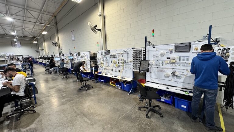
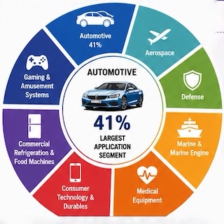
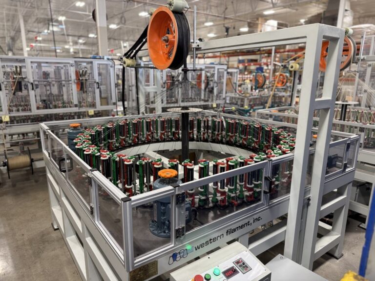
In an industry with high product volumes, like the automotive industry, rotary conveyor lines are often used in wire harness manufacturing. Figures 1 and 2 show such rotary-lines and how they move. On these lines multiple wooden or aluminum boards are mounted on a rotating conveyor.
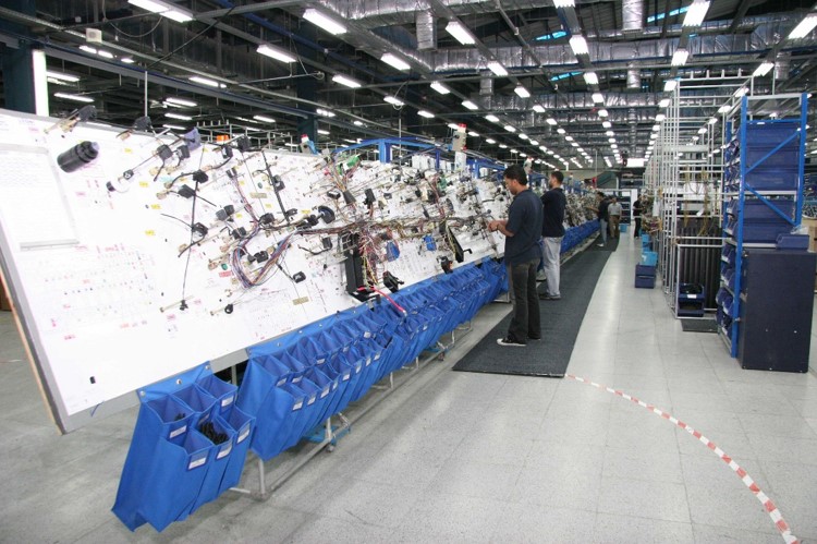
(Figure 1)
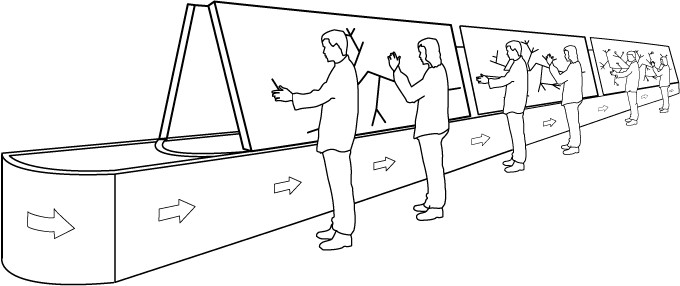
(Figure 2)
The whole rotary line is divided into different workstations as shown in Figure 3.
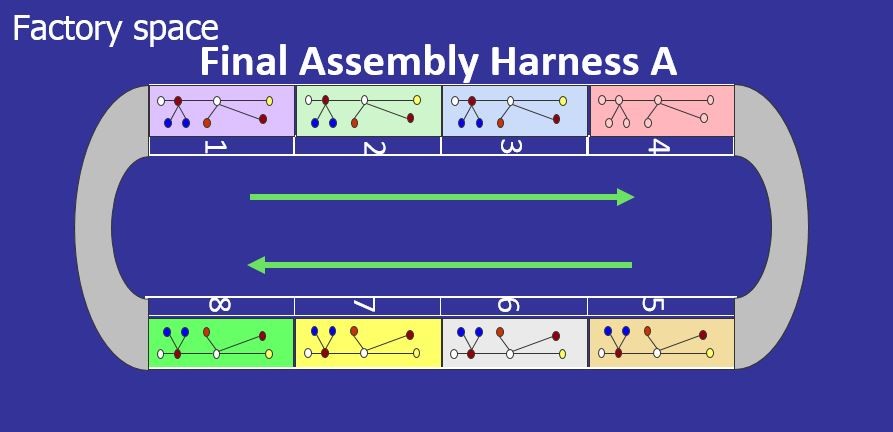
(Figure 3)
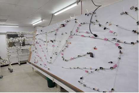
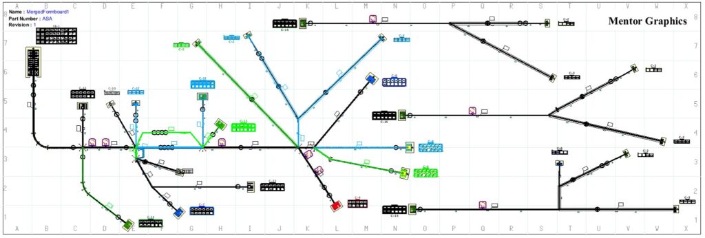
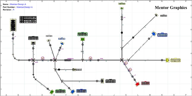
Harness designs are often documented in a 2d non-scale product design drawing. Manufacturing engineers use this product design drawing (Figure 4) to create a full-scale manufacturing drawing, called a “formboard drawing” (Figure 5).

(Figure 4)
(Figure5)
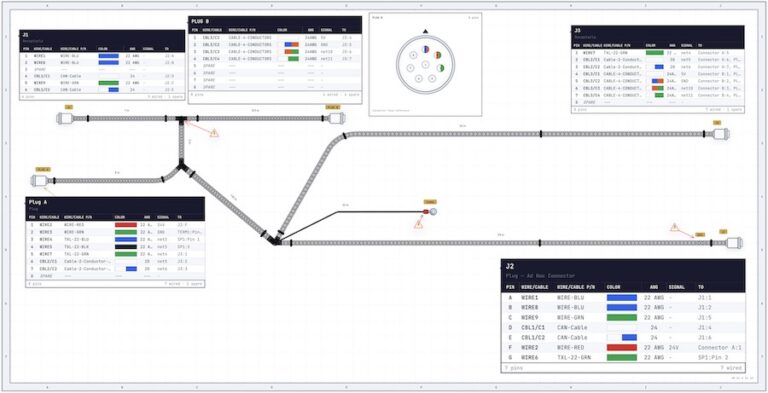
Each of the mounted boards pictured in Figure 1 shows the same formboard drawing. These formboard drawings are one-to-one full-scale representations of the harness design data, enriched with additional manufacturing information. Along with the wire harness objects, all manufacturing-relevant objects like bundle forks, connector holders, clip holders or tape position indicators are graphically represented on these formboard drawings, providing visual aids for the operators. These formboard drawings can be of single harnesses or composite-level harnesses. On a composite formboard, different derivatives of the same harness can be produced.
Based on harness design complexity, forecasted volumes, take rates and other factory-specific factors, like available equipment and factory space, manufacturing engineers make decisions upon the design of the production lines, including the number of workstations. The goal of all these activities is always to design a balanced production line design which allows them to produce the forecasted number of harnesses with the forecasted take-rates and to reach the profitability zone as soon as possible. Of course, it always takes a while to reach this zone, especially with complex products requiring a lot of human work. Operators invariably need some time to get used to the tasks they have to perform and to reach their best possible performance.
What Exactly Is A Merged Formboard?
Using merged formboards, manufacturing engineers can design production lines which allow them to produce different (but very similar) harnesses on the same line. That is, multiple production lines can be replaced by a single merged line, freeing up available factory space and other resources. Under some conditions, the productivity and efficiency of individual production lines can be increased by using merged formboards. An example will be given later in this paper.
Since on a merged formboard drawing, two or more harnesses are shown, it is a common practice to use colors to highlight which elements belong to which harness. Note the three colors on the right side of Figure 6 below:
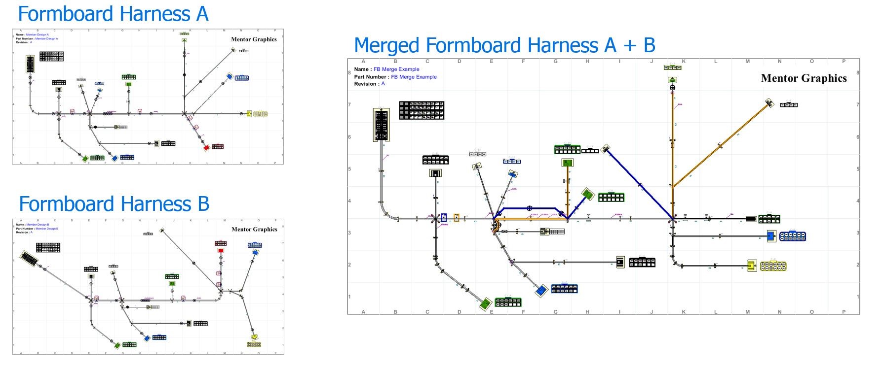
(Figure 6)
- Black: used for content which is common between all harnesses
- Blue: this content is just in one of the harnesses. Blue color was assigned to this harness
- Orange: this content is just in one of the harnesses. Orange color was assigned to this harness
The shop-floor operator knows which harnesses need to be produced. With this knowledge and the color coding, he can identify the related section on the formboard.
Commonality between harnesses is the key parameter when deciding whether to begin the merge progress, which can be somewhat involved. Generally, 70 to 80% commonality is a rule of thumb target. If there is only little commonality, the resulting merged formboard will be very complex and complicate to read and understand. This will lead to low-production efficiency since operators won’t get the required information fast enough from a complicated formboard drawing.
Example: How a Merged Formboard Can Positively Influence the Efficiency and Productivity of a Production Line?
Let’s assume we currently produce diesel and petrol (gasoline) versions of a front-end harness for a passenger car. The commonality between both harnesses is maybe around 80%. The take rate for both is very similar, forecasted at 52% for diesel and 48% for petrol. The volume is quite high. Based on this information and some other parameters, we decide to produce the harnesses on separate production lines, one for the diesel and another for the petrol version.
We balance our production lines and finish all required preparation. The final setup provides us with spare capacity so that we are prepared to handle some volume increase, as well. We start production. Our experienced operators catch up quickly to the new design process and we soon enter the profitability zone.
After some months, a significant change in take rates is noticed. The diesel take rate is going down while the petrol take rate is increasing. Perhaps the reason is a very public and contentious discussion about the drawbacks of supposedly “green” diesel engines, thus influencing consumer sentiment. Demand for petrol engines will surge as long as the future for diesel remains unclear — a well-known situation in the German market. Regardless of the cause, the trend is clear and we have to decide how to react.
In the case of our example, the immediate effect is that our diesel production line is no longer efficient. The same factory space and equipment are being used to produce fewer harnesses. More alarmingly, the spare capacity on the petrol production line may not be sufficient to handle the increased take rate of this harness.
Here are our options:
- We could set up a second production line for the petrol front-end harness to cover the increased take rate. However, this will require more factory space, more equipment and more operators, and so may not be optimal (Figure 7).
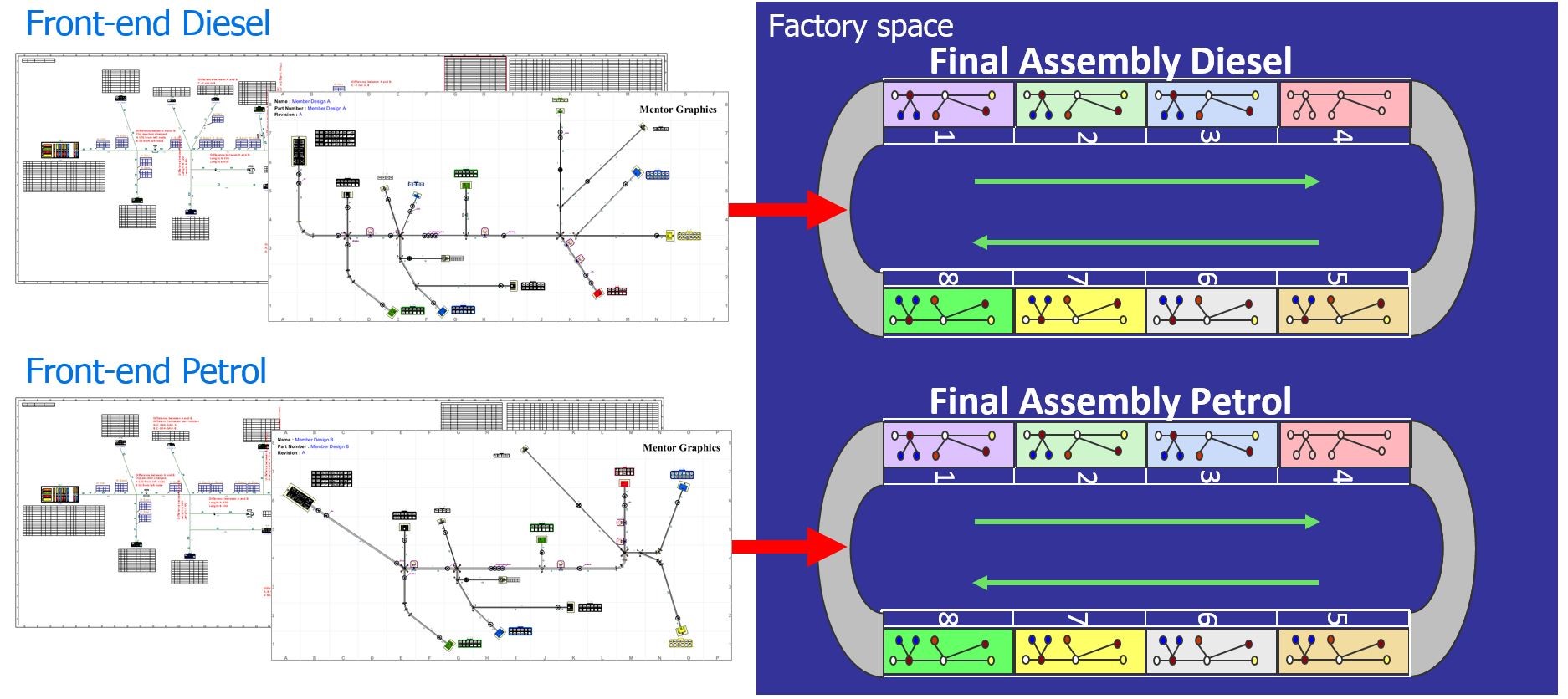
(Figure 7)
- A better approach (Figure 8) might be to redesign the diesel production line in such a way that it’s possible to produce both the diesel and petrol harnesses on the same line. In other words, we could create a merged production line using merged formboards.
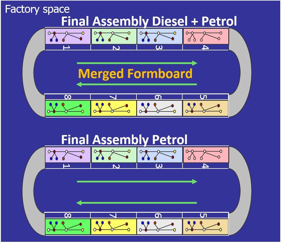
(Figure 8)
Creating an efficient and cost-optimized merged line requires merging existing formboard designs into one and ensuring reuse of most fixture and tool locations. That is, instead of again drilling all holes and placing all fixtures, engineers should only have to adjust the non-common parts of the harnesses.
Note in Figure 8 that we may well decide to leave the production line unchanged for the petrol front-end harness. With this adjusted setup, we are now able to handle the take rate changes and produce the required number of front-end harnesses without further changes on the shop floor, such as setting up an additional production line. In fact, setting up a third line would lead to low efficiency and low productivity, because the diesel and the second petrol lines would be far under their capacities. So it’s better to cover the changes with two production lines.
Despite the potential benefits illustrated by the example above, there is often resistance to even considering merged production lines because of a) the initial challenge of merging complex formboards, and b) the complexity of change management thereafter. Given current methods and capabilities, companies have to think very hard about investing the time and effort into the feasibility, implementation and maintenance of merged production lines to achieve those benefits. Sometimes they try and fail, often they don’t even try because of the risk of failure.
Of course, our example draws a simplified picture of the solution. In reality, many parameters need to be considered during the decision process. But the main message is still the same: a merged formboard can boost the efficiency and productivity of a wire harness production line, often significantly.
How Are Merged Formboards Designed Today?
Traditionally, such merged formboards are created in a highly manual process using drawing tools which are not necessarily designed for reuse and sharing of data. Even the initial step — deciding if two harnesses are good candidates to be produced on a merged production line — is a massive, labor-intensive task. Drawings need to be compared manually, with attention paid to a host of parameters such as dimensions, layout, components and their locations, required bundle fixtures and component holders.
The merge process itself is another laborious chore when done primarily using drawing tools. In fact, given limitations of most drawing tools, harness data is usually not considered at all at this step. That’s why it can take days, or in case of big harnesses, even weeks, to finish the initial merged formboard design.
Once the initial merged formboard is designed, it must be maintained. All changes made to the original harness designs must be implemented, which means updating the merged formboard. But again, since this merged formboard was likely designed using drawing tools disconnected from any data source, this is yet another time- consuming and error-prone manual task.
It is no surprise that many manufacturing engineers decide against production line optimization via merged formboards. For starters, it is often hard to find good candidates for a merged formboard. Even given significant commonality between two lines, the creation and maintenance of merged formboards is too onerous. And if engineers do go ahead, there is still room for improvement given the many disadvantages of today’s drawing tools (Figure 9).
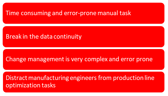
(Figure 9)
Capital: How Merged Formboards Should Be Designed
The good news is that there are alternatives to exclusive reliance on drawing tools. The Capital suite from Mentor, a Siemens Business, provides data-centric technology supporting the entire design and manufacturing flow. The list below (Figures 10,11) provides an overview of some of Capital’s key features and benefits.
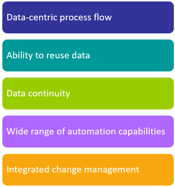
(Figure 10 – Features)
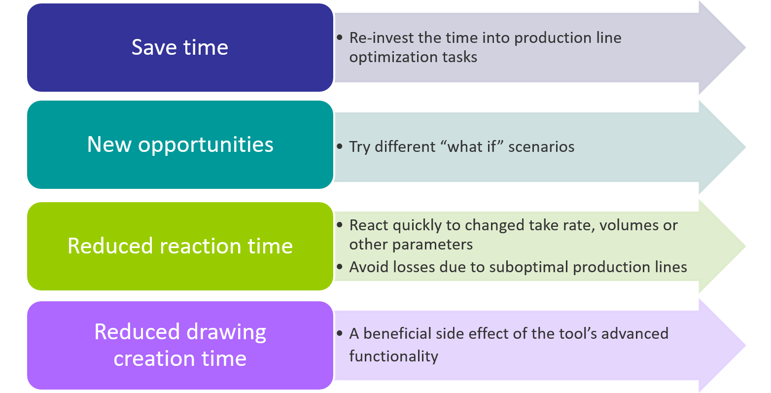
(Figure 11 – Benefits)
A harness design in the Capital suite is, first of all, a dataset, which can also be represented by diagrams. Each diagram can be styled independently, allowing engineers to create the right graphical representation for each use case. Change management is easier and more reliable since data, once entered, can be reused almost indefinitely, and because data and the corresponding diagrams remain related to each other for the entire flow.
Capital provides a perfect environment for creating and maintaining merged formboards and production lines. Manufacturing engineers can select existing formboards and compare them to find good pairs of candidates. Given data continuity, Capital Formboard Manager provides a range of support in comparing merge candidates. Calculating the actual amount of common content can be done with a click of a button. Automated merge functionality can take over many lower level, “default” tasks.
The tool supports an engineering team’s natural workflow. Knowledge about the harness, which is stored in the data, is readily available to be applied throughout the entire merge process. The tool can provide information to the engineer on the spot, a sharp contrast to traditional processes with no data continuity, where information retrieval requires a large amount of time.
Capital also dramatically reduces the time required to create a merged board. For example, the tool makes it easy to retain the position of existing fixtures on the physical formboard during the merge. Indeed, since relationships to the candidates (source designs) are maintained throughout the merge formboard process, change management is generally very fast and easy to handle. Figure 11 on the next page describes several of the benefits of using the Capital Formboard Manager to create merged formboards as described thus far.
Combined Formboard versus Merged Formboards
Combined formboards offer another means of using resources as efficiently as possible in wire harness factories. The difference is that in combined formboards, different harnesses are located at different positions. That is, spare space on existing formboards is used to produce a very different harness. This method is often used for small harnesses and harnesses with lower take rates. Combining formboards allows for many such harnesses to be produced using the same equipment and factory space. Capital Formboard Manager can be used to create and maintain these type of formboards, as well. Figure 12 below depicts one such combined formboard.

(Figure 12)
Conclusion
Capital Formboard Manager enables the creation and maintenance of merged formboards in an environment based on contiguous data flows. The tool makes it easy for manufacturing engineering department to maximize efficiency of their production lines. Transitioning from a purely manual approach relying exclusively on drawing tools to one centered on linked data vastly reduces the effort required to merge and combine boards and production lines. Capital allows manufacturing engineers to focus on what they do best, like quickly working through various line optimization scenarios, rather than operating ponderous drawing software. For harness manufacturers, this means making better shop-floor decisions and, ultimately, reaching the profitability zone that much faster as inevitable changes are made.
About the author
Frank Hemmersbach ([email protected]) is a product architect for harness design and manufacturing tools at Mentor, a Siemens business. He has 21 years of experience in the wire harness industry, including several with a major harness manufacturer within the design, development, manufacturing and IT departments. He is based in Cologne.For More Information go to www.mentor.com/capital