


Automated Electrical Testing for Harnesse – Part 2
by Ray Mumma – Cirris Systems
In a previous article on the basics of automated electrical testing (read HERE) we compared manual and automated cable / harness testing. We’ll continue that discussion by expanding on one of the topics mentioned, specifically how automated cable / harness testers make measurements. It’s a subject that is often overlooked but understanding a few basic concepts can bring more complex issues into better focus.
This is readily accomplished because, while engineers incorporate some amazing tricks under the hood, the fundamental processes are straightforward. These processes can be seen in three basic measurements – continuity, low voltage isolation, and high voltage testing. Let’s begin by examining one of the basic formulas in electronics, Ohm’s Law, which describes the relationship between voltage (V), current (I), and resistance (R) in a simple circuit with the equation, V=IR.
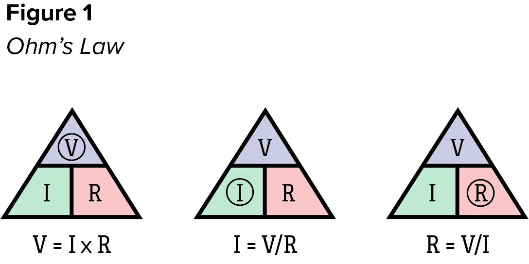
There are many excellent resources available on the internet describing Ohm’s law, so for our purposes, it’s adequate to understand the mathematical relationship between the variables. As in all similar equations with three variables, the third can be calculated if the other two are known. Some find the triangle visual helpful as it makes it easy to find the appropriate formula for calculating the unknow by covering its symbol (Figure 1). When doing the math, it’s important to remember that the unit of measure for voltage is Volts, for current is Amps, and for resistance is Ohms.
It’s also useful to understand that in a simple series DC circuit, the current at any given point is the same as the current at any other point. In the same circuit, the potential difference (voltage drop) across an unknown resistance can be measured. In the case of automated cable / harness testers, the unknown resistance is the device under test (DUT).
When performing a continuity test, the quality of the connection is evaluated by its resistance with the acceptance criteria set in Ohms or fractions of an Ohm. Generally, the lower the resistance of a connection, the better. Therefore, the test passes if the measured value is less than or equal to the specified value. Sometimes, this is referred to as a “pass-if-under” test.
The tester performs continuity tests two points at a time, regardless of the size of the circuit (more commonly called a network, or simply net) by connecting a current source to one point in the net while holding one other point in the net at ground and floating all remaining points by connecting them neither to the current source nor to ground. Some testers use the same source point for each continuity test in a net while others step through the net using the ground point in the original test as the source point for the subsequent test, as shown in the simple example below (Figure 2). Either method is acceptable.
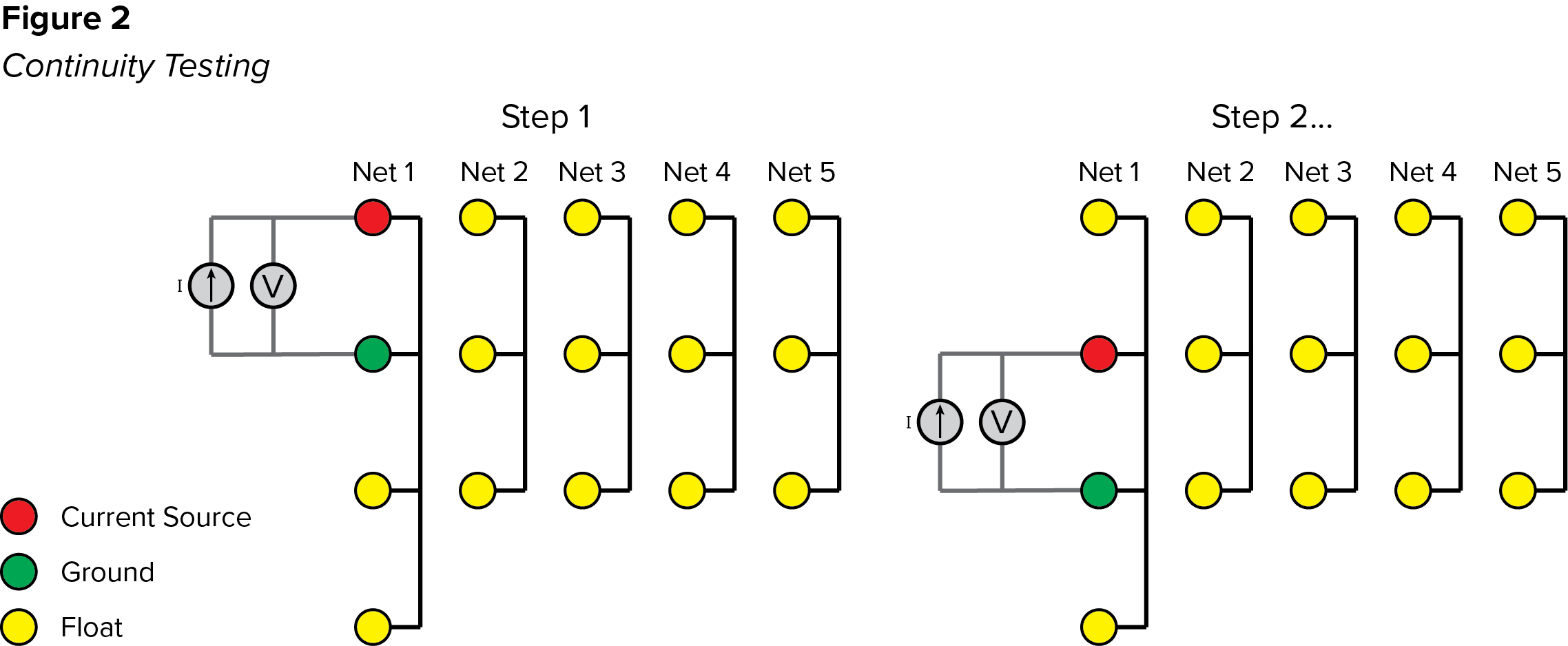
To perform each step, the tester applies a steady, calibrated current to the DUT then measures the voltage drop from the source to ground through the circuit. The resistance is calculated using Ohm’s law by dividing the measured voltage drop by the known current (R=V/I). The result is compared to the specified threshold to determine the pass or fail condition.
When performing low voltage isolation testing to ensure no unintended connections (shorts) exist, the acceptance condition is again set as a resistance value, except the pass/fail threshold is set in kilohms or megohms with the test passing if the measurement exceeds the threshold. The “pass-if-over” test is used as the greater the resistance between isolated nets the better.
To ensure that no shorts exist, all nets must be tested against all others. The exact process can vary, but for simplicity’s sake, we’ll assume that the tester applies the current source to one or more points in each net while it floats others in the net (connects them neither to the current source or ground) and holds all other points in the DUT at ground (Figure 3).
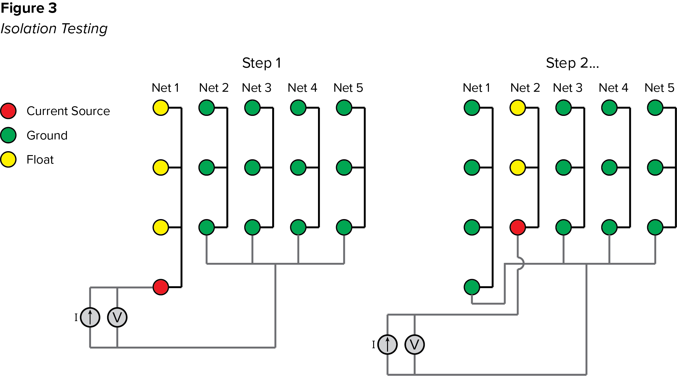
The voltage drop from source to ground is measured and Ohm’s law is again used to calculate the resistance. It steps through this process by applying the source to one net at a time. If any isolation tests fail, the tester initially knows only that the failure occurred between the source net and the group of nets held at ground. Therefore, it subsequently executes a search routine to identify the nets that are shorted.
A similar process applies to high voltage testing. However, high voltage testing typically includes two separate tests – Dielectric Withstand (DW or DWV) and Insulation Resistance (IR). Again, we’re looking at this briefly to understand the basic processes, so we’ll use simple definitions. A DW test ensures that the device under test withstands a specified voltage for a required period of time. The test equipment is designed to identify transient conditions, like an arc, in which the current spikes rapidly. An IR test ensures that the resistance between circuits meets a required minimum.
A DW test can be performed using AC or DC voltage and the pass/fail threshold is set as a maximum current in microamps or milliamps. DW is a “pass-if-under” test meaning that the test passes if the current measurement remains below the threshold for the duration of the test (lower current flow between isolated nets is better). An IR test is always performed using DC voltage with the pass/fail threshold set as a resistance, typically megohms or gigaohms. IR is a “pass-if-over” test meaning that the test passes if the measurement is greater than the threshold (greater resistance between isolated nets is better). Typically, the DW test and IR tests are performed sequentially with the DW test performed first. In both cases the measurement is made between nets that are expected to be electrically isolated.
There can be variations in the process, but like low voltage isolation testing, each net must be tested against all others. A standard process for doing this is to connect a high voltage source to all points in one net while all other nets are held at ground (Figure 4).
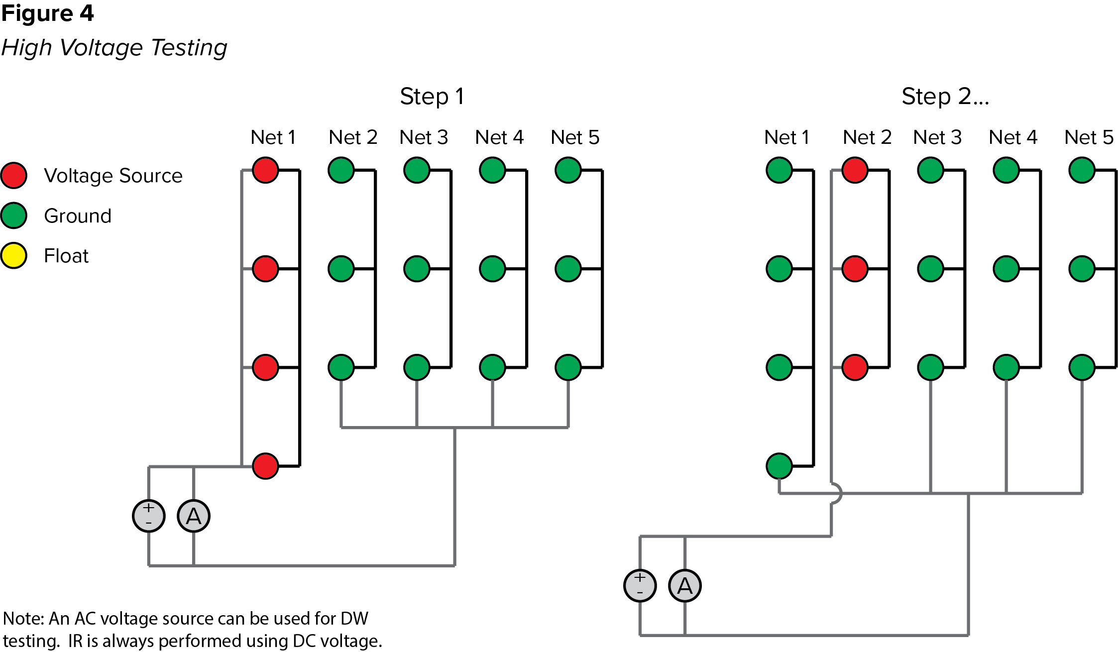
At the same time the current flowing from source to ground is measured. The measured current is used to determine the pass/fail status of the DW test while Ohm’s law is used to calculate resistance for the IR test by dividing the voltage by the measured current (R=V/I). The calculated resistance is then compared to the IR threshold to determine the pass/fail condition. We’ll cover high voltage testing in greater detail in the future, but for now it’s enough to say that very little current is expected to flow between nets that are electrically isolated.
As with a low voltage isolation test, if a failure occurs, the tester only knows it occurred between the net at high potential and the group of nets held at ground. In the event of a DW failure, the tester will report the net that was at high potential, but it won’t usually execute a search to identify the specific net to which the failure occurred. Primarily, this is because arc events are not reliably reproducible, which often makes the search unproductive. However, IR failures are typically reproducible and testers with search capability can, therefore, identify the net to which the failure is occurring.
Hopefully, this brief summary will remove some of the mystery that can surround automated electrical testing and help build a foundation for better understanding of the testing process in general.
Cirris has been providing electrical test solutions for cables, harnesses and complex electrical assemblies since 1984. For more information, visit www.cirris.com.