


Automated Electrical Testing for Harnesses
By Ray Mumma
This is the first of a series of articles about the basics of automated electrical testing. Think about the series as answers to questions you were afraid to ask. We’ll start with simple concepts and mix in a few more complex topics over time, so hopefully there will be a little bit for everyone. As always, the best place to start is at the beginning.
What is automated (or automatic) electrical testing and what are its benefits? To answer these questions, we must first consider the characteristics of the products with which we are working. Electrical assemblies, whether simple cables or more complex assemblies like wiring harnesses, printed circuit boards or wired cabinets, all include interconnections. For the purpose of this discussion, these interconnections are most often made using insulated wire or copper traces on printed circuit boards and they provide the paths used for routing electrical signals. These interconnections are referred to as circuits or electrical networks (nets). Nets may have two or more terminations, usually made in connectors, lugs, stripped wire ends, terminal strips etc.
The quality of connections can be quantified by their electrical resistance measured in Ohms (indicated by the Ωsymbol). Connections with too high a resistance are most often the result of manufacturing defects. Assembly drawings or associated specifications typically define what constitutes “too high” by specifying the maximum allowable resistance of a “good” connection. Occasionally, drawings will neglect to include this information and we’ll discuss in a future article how to calculate this pass/fail threshold. For those who like to read ahead, the IPC/WHMA A-620 specification provides a reliable source of information on the topic.
Another critical characteristic of wired assemblies is electrical isolation. It’s well understood that the quality of connections within a circuit is critical, but the electrical isolation of circuits is of equal importance. The quality of the isolation can also be evaluated by a resistance measurement, but instead of expecting a very low resistance as in the case of a connection, a very high resistance is expected between nets and between any positions in the assembly that should have no connections, such as empty, unused positions in connectors.
Although it’s an incomplete description, some may refer to this type of quality assessment as “opens and shorts” testing. The description is incomplete because the resistance of a connection may be higher than allowed without being an open, which is defined as no connection. Opens testing may also be described as a continuity check and shorts testing referred to as isolation or insulation resistance testing. Regardless of the terminology used, it may help to think of a continuity test as a “pass if under” test, meaning that a “good” condition exists if the resistance measures less than or equal to the pass/fail threshold, while an isolation test is a “pass if over” test, meaning that a “good” condition exists if the measured resistance is greater than or equal to the pass/fail threshold.
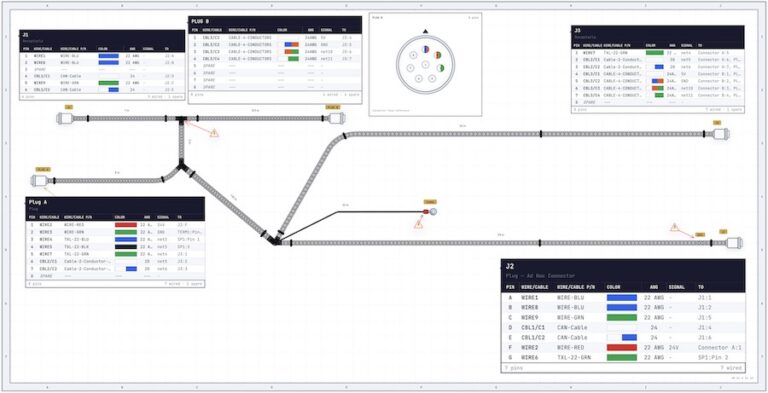
With that understanding, let’s examine what would be involved in manually testing a very simple, sample product using a multimeter to perform the resistance measurements. Our example is a one-to-one cable with seven conductors terminated in two connectors and a shield connected to both connector shells.
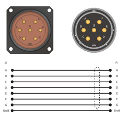
To perform continuity testing of the assembly it would be necessary to measure the resistance between the terminations and compare the measurements to the pass/fail threshold for a total of eight tests.
J1-A to P1-A
J1-B to P1-B
J1-C to P1-C
J1-D to P1-D
J1-E to P1-E
J1-F to P1-F
J1-G to P1-G
J1-Shell to P1-Shell
For more complex assemblies the required number of continuity tests could be calculated by using the formula (nTerminations – nNets) where nTerminations is the total number of terminations in all nets and nNets is the number of nets, or 16-8 = 8 in the sample cable.
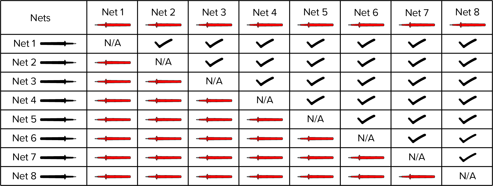
Performing isolation testing on the assembly is more complicated as it requires the resistance of EACH net to ALL other nets be measured and compared to the pass/fail threshold. We can calculate the number of required manual isolation measurements using the equation (n (n-1) /2) where n is the number of nets. In our example, this would be 8 x (8-1)/2 = 28. The required number of measurements can be visualized in Table 1. As a net must be measured to each other net only once, working across the table it can be seen that a total of 28 measurements are needed to test each net against all others.
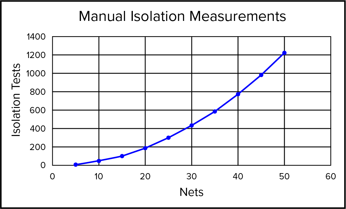
We can see in the chart below that as the number of nets increases the number of isolation tests required quickly grows beyond practical manual implementation. The result, shown in Figure 2, is that when manual testing is used, isolation testing is often skipped altogether.
This is the point at which the basic benefits of automated testing become obvious. Although it’s a dramatic oversimplification, it may help to think of an automated tester as a multimeter with many leads, instead of only two. This is accomplished by switching the measurement capability of the tester through a relay matrix controlled by software.
To take advantage of the tester’s capabilities, it’s necessary to connect the tester to the product. This requires some type of test fixture. A simple example would be test cables with connectors on one end that mate with the tester and connectors on the opposite end that mate with the product. This is an investment not required with manual testing. However, with the product connected to the tester, the tester can automatically switch the relays to rapidly perform each continuity measurement, compare the measured value to the threshold and determine a pass/fail condition.
When performing isolation testing, the tester has a distinct advantage over manual testing. As a benefit of its architecture, instead of performing measurements from each net to all other nets one pair of nets at a time, the tester can measure from one net to all other nets in one measurement. It does this by applying a voltage to one net while holding all other nets at ground, measuring the current and using Ohm’s law to convert the measurement to resistance. (Note that the exact method used by different equipment will vary, but it’s helpful to simply conceptualize the voltage being applied to one net while all others are held at ground.) Only if a failure condition is detected, is it necessary to measure the resistance between nets in individual pairs to identify the net to which the failure occurred. The result is that a typical, thorough test of the assembly, including continuity and isolation testing, can be accomplished in a matter of seconds without the possibility of human error.
While our sample product was a very simple assembly, it’s still readily apparent that automated testing provides a more reliable result, especially considering the differences between manual and automatic isolation testing. On the financial side, it’s important to recognize that while automated testing requires an investment in equipment, test fixtures, and programming, a fair comparison with the cost of manual testing cannot be made without including the labor for isolation testing. It must also be noted that the per unit cost for automated testing declines with higher quantities, repeat runs and product complexity while the per unit labor cost for manual testing may decrease slightly with higher quantities based on the learning curve, but it will remain relatively constant. Manual testing higher quantities also leads to worker fatigue and inattention, which increases the probability of errors. Finally, regarding product complexity, automated electrical testers typically can perform more than simple continuity and isolation testing and often provide the capability to test components such as resistors, diodes, capacitors and depending on the equipment, some add the capability to perform high voltage dielectric withstand and insulation resistance testing, all of which expand the advantage of automated testers.
Next session we will discuss how automated testers perform measurements.