


Top 10 Concerns for Signal Connections

By Andrew Bogaczyk, Joel Boone, and Loreen Katz, of Phoenix Contact
Introduction
Where do you find signals in industrial/semi-industrial settings? Everywhere. Generally, devices such as sensors, actuators, switches, valves and cameras need signal connections for control and monitoring. As more and more devices are added to the plant floor, secure and reliable connections are of absolute importance. Devices today must handle a wide variety of functions and include features that will ensure cost-efficiency, reliability and safe operation.
Based on customer comments and surveys, we have identified the following concerns that end users have regarding their device connection technology choices.
Cost
Cost is frequently the driving factor when deciding on a connector style for device installation. Engineers and buyers consistently require cost-effective connectors that provide quality and value and meet the application requirements. However, purchasing personnel can overlook the applied costs versus the component costs. Extensive labor rates and downtime due to troubleshooting and loss of throughput during lengthy installations must be considered in addition to the component costs. A solution that can save time and money not only includes the best component pricing, but also brings more efficiency to the operation and installation of a device. Equally as important, connector manufacturers can evaluate the use of application-appropriate materials and designs, as well as global manufacturing efficiencies to offset some of the impact of rising raw material costs.
Environment
The environment where the connection is made often dictates certain criteria. For example, electromechanical interference (EMI) from drives, motors and other nearby noise-producing equipment can cause loss or unreliable signal transmission. Using shielded connectors and cabling will eliminate concern for EMI.
There are several methods of shielding a cable; however, the most reliable manner is a braided copper screen with a minimum of 85 percent coverage around the conductors. The copper braid is terminated to the head of the connector on both ends of the cable to provide protection from EMI from the point of connection throughout the whole cable assembly.
Additionally, elements in the environment such as dirt, water, oils, chemicals, high/low temperature and sunlight can affect the performance of a connector. To alleviate these concerns, selecting a product with ingress protection rating of IP67 or higher and Viton gasket materials will prevent corrosion and damage of the housing.
Vibration
Mechanical stress during installation or operation of a device can cause substantial vibration to the PCB and connector contacts. Therefore, many industrial applications require connections that meet vibration and shock resistance in accordance with IEC 60512-4 or EN 50155. Connectors designed to these standards will have construction elements such as locking screw thread, radial o-rings, mounting flanges, set screws, potting of the body cavity, which all protect against vibration.
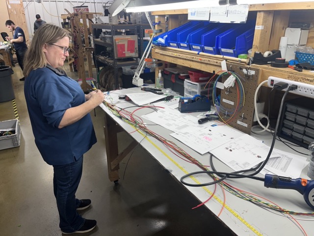
Spring technology is another common method to protect against vibration. Spring technology has become the choice termination technology for the rail industry (Figure 1), because the spring termination can sustain a constant force on the wire throughout many environments prone to vibration.

Figure 1. High-vibration industries, such as railroad, need connectors that will meet strict requirements to withstand shock and vibration.
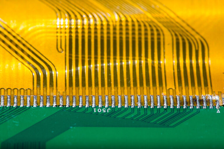
High-density
The overall trend in device manufacturing to reduce PCB size and increase I/O count has inspired connector manufacturers to offer high-density products. Many I/O terminations need to be made where space is limited, creating the challenge of connector density. This miniaturization limits the amount of PCB real estate dedicated to I/O connections. Multi-level terminal blocks and compact connector designs allow for more terminations in the same small footprint.
Signal integrity
Any breakpoint along the connection can affect signal integrity, but this is mainly a concern at the contacts. Without a reliable connection, system maintenance could become extremely costly, and resistance due to fretting corrosion could cause signal loss or open circuits.
To prevent fretting corrosion, two primary methods are employed. With tin surfaces, it is important to have a stable connection interface. This is accomplished with “high” contact forces, which assure that fretting corrosion due to micromotions does not occur. Gold-plated contacts are another way to ensure a reliable connection. Gold is a noble metal with good electrical properties and is not subject to corrosion issues. Gold-plated contacts do not require high contact forces for protection against corrosion. Therefore, gold is the preferred method for high pin count connectors, where high contact forces would lead to undesirable connector insertion and withdrawal force.
Fast connections
Making fast connections is usually necessary for an installer, especially when the job requires numerous connections. The faster the installation is, the less cost involved for the project. Often, these connections are located in hard-to-reach areas or in poor lighting, making it difficult to see. Additionally, finger fatigue and cross-threading can plague the success of fast installation.
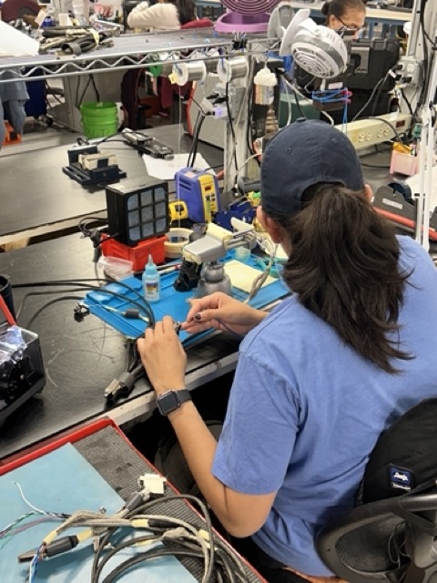
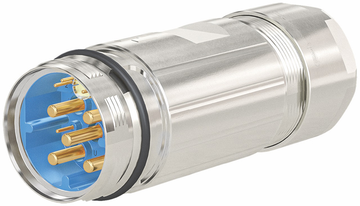
Some of these issues can be prevented at the design stage by using connectors with fast-connection technology (Figure 2), such as spring cage or insulation-displacement (IDC) and quick-locking or push-pull pluggable connections. These connection technologies allow more connections in a shorter time. Several time studies have shown that IDC can save 60 percent more time than traditional screw wire termination. Half-turn circular connectors can save up to 90 percent more time than the traditional threaded connectors.
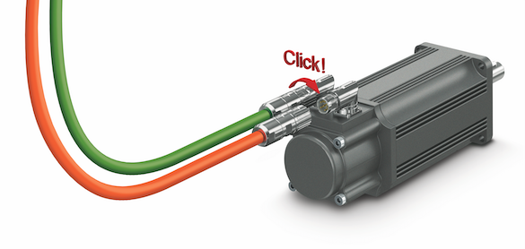
Figure 2.
Miswiring
The most common errors that technicians make in the field are miswired I/O connections. Not properly terminating wires to the correct terminals can delay system commissioning and device start-up. Using color-coded terminal blocks or inserting markers on all wire/connection points can eliminate confusion and reduce time spent on troubleshooting errors in the field.
Quality, environmental and safety requirements
In today’s global economy, engineers and product designers require a trusted connector source around the world. Partnering with a manufacturer who upholds strict quality, environmental and safety programs is essential. The manufacturer who meets international standards organizations’ requirements will be a reliable partner.
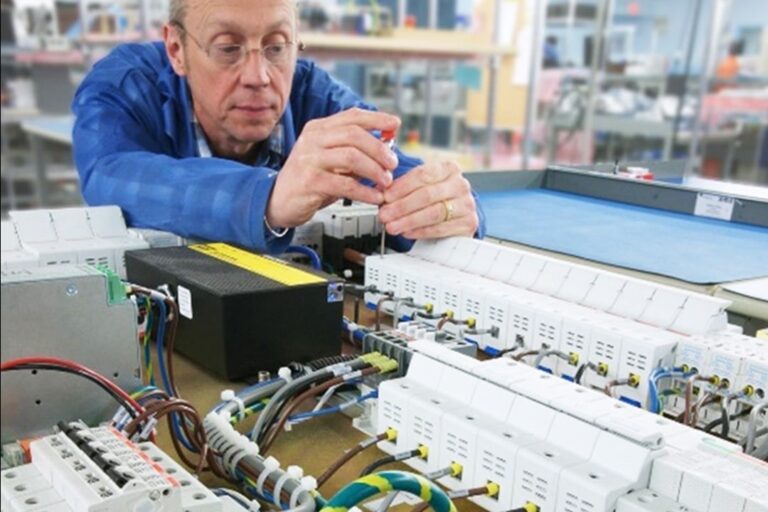
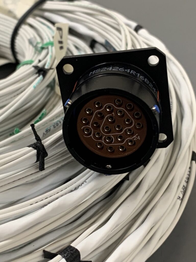
Connectors that conform to industry standards and have agency approvals (RoHS, CSA, and UL) eliminate concerns with inspectors and users of the finished device. Connector manufacturers with in-house laboratories offer product testing and qualified solutions from prototype to series production (Figure 3).

Figure 3. The environment where the connection is made often dictates the required criteria. For example, connectors used in the food and beverage industry must meet washdown requirements.
Mismating
Mismating similar connections is another common concern – that is, where multiple identical connectors are used on the device. The confusion of plugging the wrong connector into the wrong socket is caused by having a row of connectors with the same configuration (thread size, footprint, pin spacing, pole count, etc.). In these instances, the addition of a keying or coding element can help to distinguish the appropriate cable or terminal block connection. Some circular connectors will offer standard coding such as A, B, C, D, S, T, X or Y. Terminal block connectors can be keyed in several different patterns, allowing only the correct plug to be mated with the appropriate socket. Cable labeling or color coding can also reduce mismating potential.
Mounting
Improper mounting of connectors can also cause problems. Many PCBs require plenty of hand-placed components. Also, many connectors can appear very symmetrical in design. Thus, it is quite common for such connectors to be positioned 180 degrees from proper alignment when being hand-placed. Polarization pins or non-linear pin arrangements can eliminate this very simple, but common, mistake.
Conclusion
When choosing an industrial signal connection, the user must consider many variables to determine the right connector for the job. Phoenix Contact’s industrial plug connectors and PCB connectors work together to create signal connections for any application, on or off the printed circuit board. For more information about connectors for control, power, and networking, visit www.phoenixcontact.com/connectconfidence.
Many thanks to Andrew Bogaczyk, Product Marketing Manager, Joel Boone, Product Marketing Manager, and Loreen Katz, Integrated Marketing Manager at Phoenix Contact who authored this article.
———————-
Captions
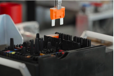
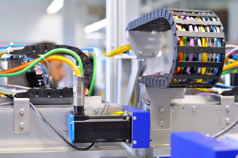
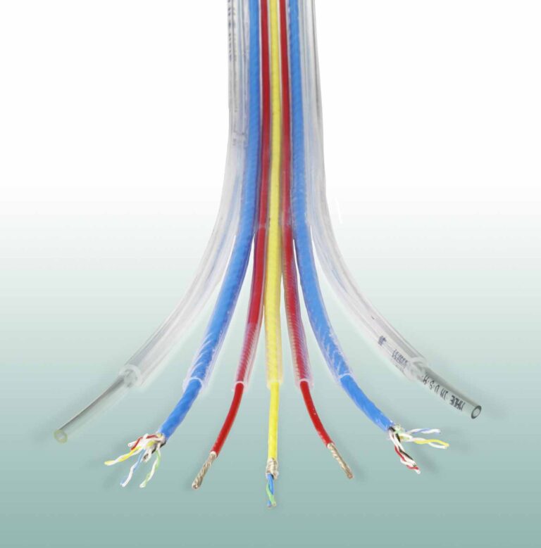
Lead image: As PCB design becomes more complex, designers need to consider many factors to choose the best signal connectors for a specific application.
Figure 2. Connectors with fast-connection technology, such as the ONECLICK quick-locking system from Phoenix Contact, can reduce installation time and cost.