


The Basics of Mechanical Wire Stripping
Part 2 of Soldered Wire Termination Series
This is the second in a series of articles that will continue to review soldered wire terminations. In a previous issue (March/April 2020) discussed) wire preparation, specifically thermal wire stripping, was covered. The focus of this article will be mechanical stripping of wires. The use of high-quality mechanical strippers that are used for precision stripping will be discussed.
Make sure and stay away from the common wire strippers found at the big box stores that are used for stripping electrical wiring used in your house (Fig 1).

Figure 1.
Select a set of strippers that have precision blades such as this pair of mechanical strippers which has a flat sandpaper like area that grips the insulation instead of sharp metal ridges that will damage the insulation (Fig 2).

Figure 2
Make sure to look at the blades to verify that they align correctly in order to make sure that the conductor will not be damaged by the blades (Fig 3).
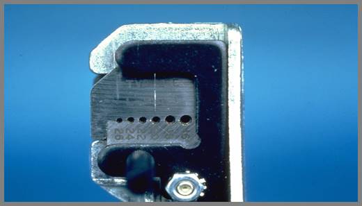
Figure 3
The blades should also be matched to the type of insulation that will be stripped. If a set of blades that is designed for PVC insulation is used on PTFE insulation the results will be less than idea at best. The last article discussed that using mechanical strippers on smaller than 20AWG wire might damage the wire such as stretch the conductor and lower the current handling capability of the conductor. On 22AWG and smaller conductors it would be recommended to use high strength copper alloy wire to help mitigate that issue.
Next, we’ll discuss the steps involved with mechanical stripping.
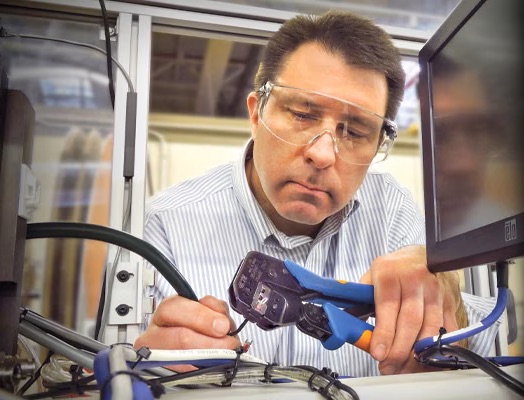
Step 1: Place the wire into the jaws of the stripper perpendicular to the blades (Fig 4).
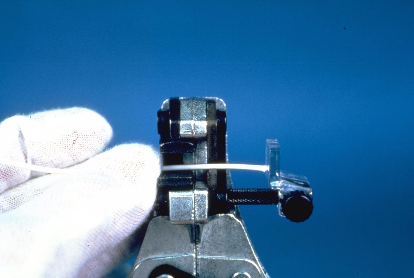
Figure 4
If the wire is not straight the blades can nick some of the conductor strands. In the photo this stripper has the optional wire stop that can be used to achieve identical strip length on multiple wires.
Step 2: Squeeze the handles together with consistent pressure until the blades cut the insulation (Fig 5).
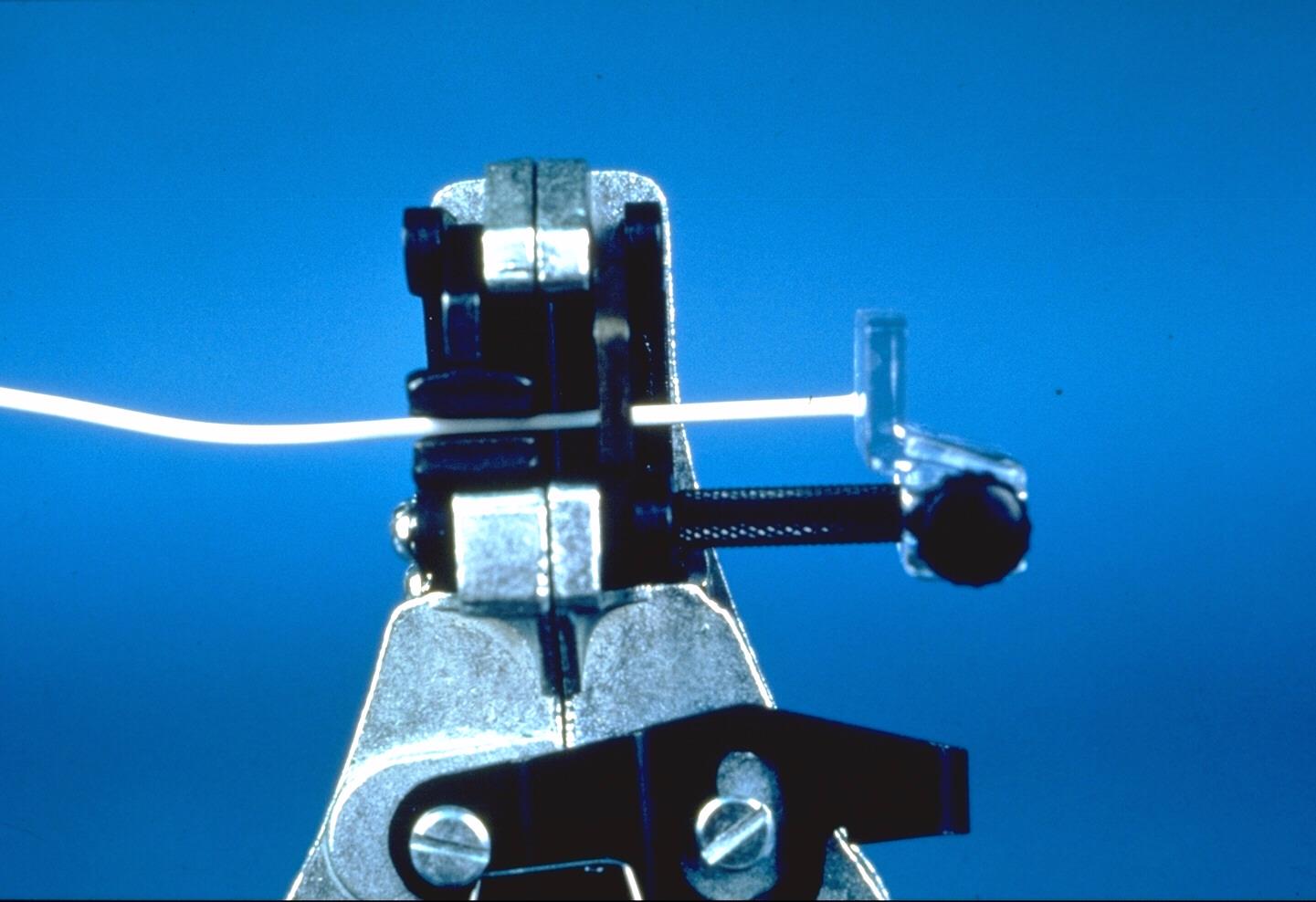
Figure 5
Step 3: Release the handles and remove the wire (Fig 6).
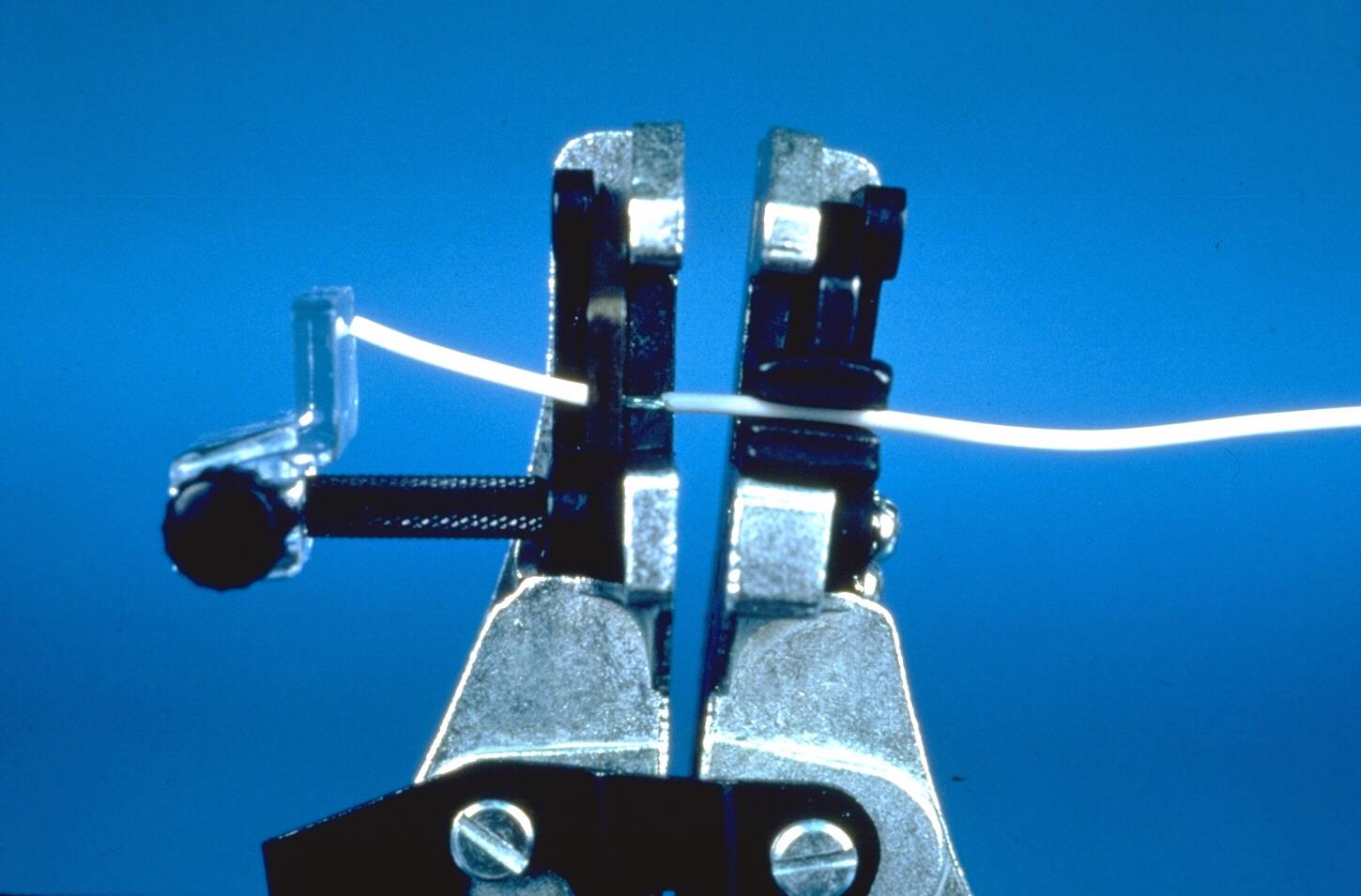
Figure 6
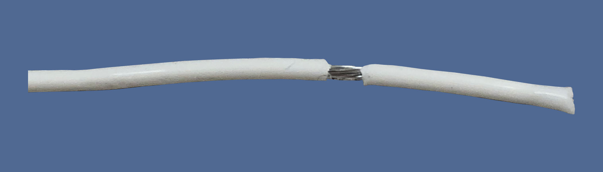
The insulation slug may also be left in place if just kitting the wires for later use to protect the wire from damage until ready for use (Fig 7).

Figure 7
Step 4: Remove the insulation slug from the wire (Fig 8).
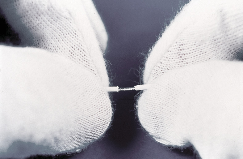
Figure 8
The best way to maintain the natural lay of the strands is to slowly twist the insulation slug in the direction of the strand twist as you are pulling the insulation slug from the wire.
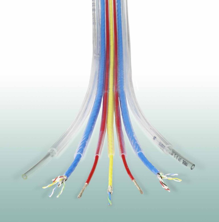
Step 5: Final product.
Inspect stripped wires to make sure that they meet your quality requirements (Fig 9 & 10).
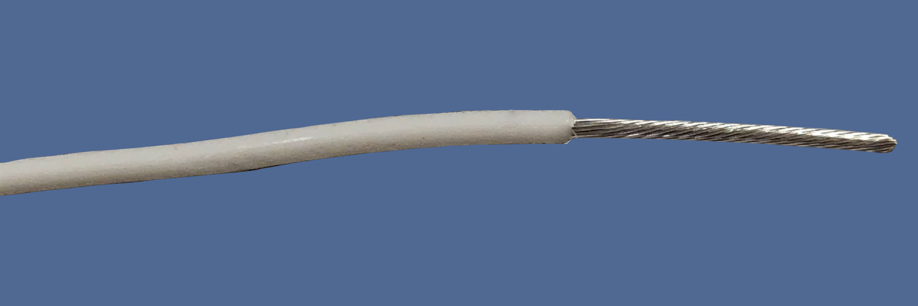
Figures 9 & 10
Now that the process of wire stripping has been covered in detail the next issue will address tinning of wires for use on soldered terminals and crimping of wires onto contacts.
STI is a multifaceted technical organization whose common goal is to provide support through products and services in the field of electronics manufacturing including IPC/WHMA A-620, J/STD. There are online or live classes available in various locations. Visit www.stiusa.com.