


Quality Assurance
by John Belovarac – Mecal by Starn
Every customer wants to know how their products are measuring up to some standard, whether it is our own Mecal guide to quality crimping, IPC-620, Volkswagen 63033, USCAR 21 or something else. As a customer of Mecal, you have the option to either follow our standard, or supply us with the standard you would like us to follow and we will do our best.
So, lets unpack the Mecal standard and explain in detail what it is saying. It is broken into two sections, unacceptable and acceptable. The values are put into pictures for easier understanding. Most of the information is widely accepted by others as being the best working conditions. This is not revolutionary information, but good guidelines that unless taught, may not be instinctually understood or recognized. It is simplified and may be best directed toward entry level personal.
Wire preparation:
This can have a significant effect on the quality of the crimp. If you are preparing by hand, you must use a high-quality pair of cutters to cut the wire cleanly and squarely. They must not be allowed to crush the wire strands at the tips or leave a burr from not cutting smoothly. The wire must also be held as close to a 90-degree angle to the cutters as possible. If this is not square, then the measurement of the stripping length and overlay or brush (measured distance from the end of the crimp to the end of the wire) is hard to establish. Keep your cutting tools sharp.
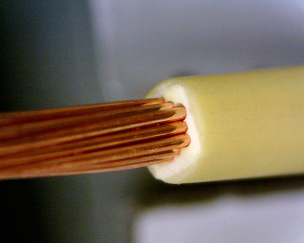
Assuming you are stripping with a bench top stripper, it is important to get the proper “stripping diameter”. 7 and 19 stranded wire are in a nice round bundle and you can get the square cut of the blades to come as close to the strands as possible and cut clean. Other wire configurations may not be as round (more egg shaped) and the blades will come closer to some of the strands than others. If they’re too close they will damage some of the strands. If they’re too far away you will need to pull more uncut insulation to remove the slug. Understanding that you have cut into a square shape around a round bundle of wire, what is not cut cleanly must be pulled or ripped apart to remove the slug. Most insulation types rip apart easily, but some do not and can either tear, stretch or leave pieces of trash insulation behind, which are all unacceptable. On the acceptable side would be a good square cut of the wire strands with a clean cut of the insulation at the precise length required by either the terminal manufacturer or by comparing to the terminal itself to insure a proper overlay or brush ahead of the crimp and the insulation cut present between the wire and insulation crimp window (more on this later).
There is a set of grippers that hold the wire while the cutting and pulling of the slug. The tension on these grippers can be adjusted and can also cause damage to the insulation. Caution must be taken to not grip the wire too tight.
A solution to the difficult insulation type is a higher quality rotary stripper that take the same V blades and spin them around the wire cutting much cleaner.
Insulation crimping:
ICH (Insulation Crimp Height), ICW (Insulation Crimp Width).
For our conversations pertaining to terminal position from here on, let us consider the end of the terminal that is the connector portion as being the front, and the end that is the crimping areas as being the rear.
There are 4 basic insulation crimping shapes. The F crimp (looks like a sideways B, or a heart) is the most prominent. Also is the bypass, where the two wings are tapered and create a round shape with one wing toward the front and the other toward the rear. Next is a round shape that is used more for around a seal and usually ends up measuring the same height and width. Finally, is an overlap crimp where one wing is under the other. Overlap is not the same as round. The name F crimp also pertains to the wire crimp. There are many opinions on what a proper insulation crimp looks like, and most standards are a little vague on this topic. Most only offer what is unacceptable and beyond that is up to you. It is important to not lose focus on the intent of the crimp. Which is to hold the wire from moving around- left and right, up and down, vibrating, all allowing the wire strands to start rubbing in the bell mouth area and possibly causing wear and breakage.
Some of the unacceptable conditions are as follows.
• Piercing the insulation: This is critical and special attention needs to be paid as this issue can arise often. As the crimp is made and the wings are forming down against the insulation, it should not be so tight that
it forces the wings into the insulation and splitting it open.
• Most terminals are made for a specific range of insulation size, and when you are out of that range, you can see problems, like the wings piercing the sides of the insulation (too large of insulation diameter) or the wings having to curl under themselves (insulation too small of diameter), this still being an acceptable crimp.
• Some standards have a minimum amount of contact, like 270 degrees around the insulation. Obviously one wire size would be optimal and with the right insulation crimp size, 270 degrees minimum is easily reached. Change your insulation diameter and this amount of contact can change to be an unacceptable condition.
• When determining a good insulation crimp, I teach to always continue to decrease the ICH until you have gone too far. It should become obvious when you get there, then you can increase a bit to arrive at the acceptable range.
Wire crimping:

CCH (Core Crimp Height), CCW (Core Crimp Width).
• This is the heart of the matter. This is the mechanical and electrical connection of the wire to the terminal. The correct CCH and CCW are essential to achieve the proper compression ratio and pull force, which are the two main parameters to understand (more on this in checks and evaluations). Properly designed and maintained crimping tools are necessary to meet all the different parameters of any standard you choose to use.
• To back up to a comment made earlier, the position of the wire relative to the terminal can change the appearance of the overall crimp without changing any other adjustment. Therefore, high-quality wire stripping is essential. To simply see the insulation cut somewhere between the wire and insulation wings may not be enough, but it must be in a place and be maintained at this place. Same for the brush (overlay) which you may need to ensure is in a precise location, regardless of the tolerance.
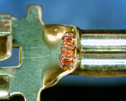
• Symmetry is probably the most significant sign of proper applicator adjustment. It is directly related to the centerline of the terminal wings and the centerline of the crimping tools. If the two are not in alignment to one another, then one wing will curl into the strands longer than the other. The adjustment would be to move the long curl of the terminal wings closer to the centerline of the crimping tools. Symmetry is one of the hardest specifications to measure or see. You need specific cross sectioning equipment to see the symmetry. What is not acceptable is one wing curling so far that it is colliding with the bottom or the side of the terminal.
• Another unacceptable condition is not having the wings contact each other at the top. This is a clear indication that the wire section is too large for the terminal.
• Gaps around the strands is another unacceptable condition. When looking for gaps, you must make sure your cross-section cut is not through one of the serrations in the terminal. Gaps around the strands would indicate you have not reached the optimum CCH yet.
Checks and evaluations:
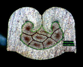
• Compression ratio of the strands is measured by cross section equipment and is the difference between
the area of all the strands added together in the loose state, to the area of the strands after crimping. The Mecal standard has the compression at 17% to 24% reduction in size. Tighter is not always better.
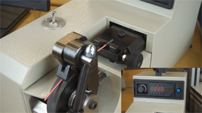
• Pull test is probably the most common method of detecting a proper crimp. Although achieving an acceptable pull test value is a good thing, it does not measure any of the other parameters needed to make a good crimp. Therefore, if you get a bad pull test, you need to dig deeper into the crimping shape (with cross sectioning equipment) to determine what is wrong in order to make the proper correction.
• Compression ratio vs. pull test.