


Researched and Compiled by:
ETCO, Inc.
Research and Development
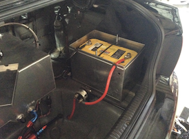
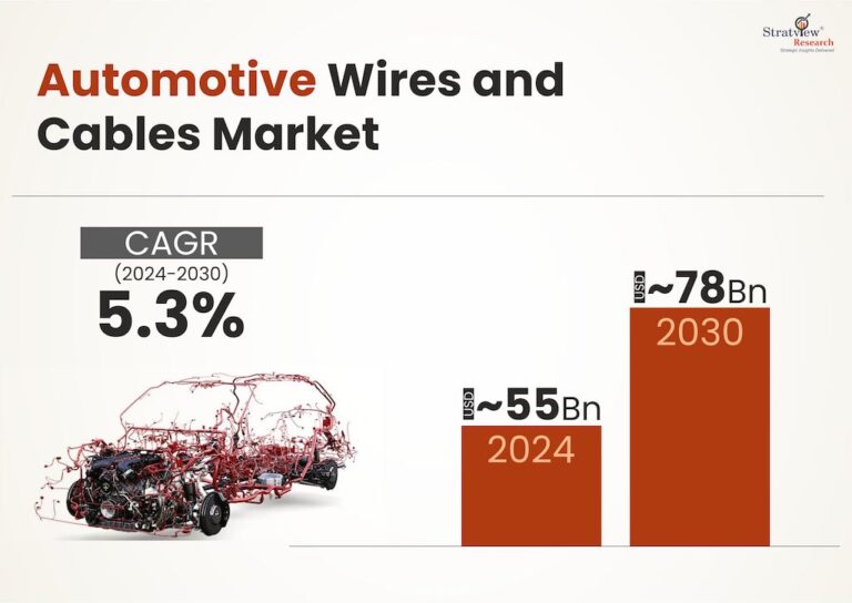
Problems within the electrical system have long been an issue with automobiles. One of the most common areas for an electrical circuit failure is with battery connections. The heavy-duty terminals required for large AWG wires like those used on battery connections are gaining attention with manufacturers that provide terminals to the Automotive Industry. Electric terminal manufacturers utilize a good portion of their engineering resources focusing on the development of new product or improving existing terminals for an industry that is also focused on, costs, improving fuel mileages, reducing the use of lead ( RoHS) and vehicle weights.
Many things have to be considered when developing a terminal for heavy duty automotive applications. This report will share several concerns vital to manufacturing a robust, heavy duty automotive electrical connection that must meet or exceed customer specifications and SAE standards.
1. Material selection for terminals
Since the implementation of the RoHS directive, lead terminals are being replaced by those made of other lead-free materials. Terminals can be manufactured from steel and exotic alloys with various plating options including bright and matte finishes. A great choice of material for a heavy-duty battery terminal is Tinned Brass. Its properties are superior to Lead for electrical conductivity, corrosion resistance, tensile strength, hardness and durability. All of those metal characteristics provide for an optimal heavy-duty terminal. For those looking to reduce weight a lead-free stamped battery terminal made of Tinned Brass is an idea substitute for a heavy cast terminal.
2. Terminal Design and Features
A good engineering team will develop a terminal design that allows it to be part of the best connection possible and include design features that facilitate the terminals processing by the wire harness manufacturer. Some things they will consider beyond the metal choice are:
- Overall size and wire range of terminal. Determine how much metal is needed to produce the best terminal. The Length of terminal and material thickness are evaluated.
- Crimp area of terminal. The pocket / U shaped area of the terminal that will form the bond to the wire. This section is designed with specific coin, rib and serration features that will aid in this union.
- Mating area geometry. The portion of the terminal that will mate with its opposite to form the connection. This requires coupling features that will ensure the integrity of the circuit. Matching forms will provide maximum surface to surface area contact that will maintain a solid bond.
- Layout considerations for a terminal’s production will include determining a side by side or end to end configuration and its feed length. Attention is given to the direction of the terminal strip as it will need to be wound onto reels in a fashion that compliments the needs of the application process.
3. Terminal Crimp
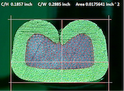
The crimp is a solder-less termination method used to fasten the terminal to the wire. There are several styles of crimp terminations. One type incorporates a straight cylinder shape located at the back of a terminal where an insulation stripped portion of a wire is inserted. The cylinder is then pinched onto the wire. The collapsed portion of the cylinder forms the union between the terminal and the wire strands. Another type of crimp preferred by most quality wire harness manufacturers is the F type crimp. This type of crimp has a U-shaped portion at the back of the terminal designed to form an envelope around the exposed wire strands and be swedged between a sized punch and die, also known in the industry as roll tool and anvil. The resulting connection of the F type crimp is a union so tight that every wire strand is distinctly reshaped by the geometry of the crimp tooling and the compression force. A good crimp is imperative to having good retention to wire. Proper tooling and terminal selection in the recommended equipment and with correct settings will consistently yield quality crimps like the one shown below. A good terminal manufacturer will develop and provide tooling that will offer the best possible crimp. One that has a properly flared bell mouth on the wire side to reduce cut strands and yields a joint that offers optimal wire retention with the lowest electrical resistance.
4. Terminal Variety
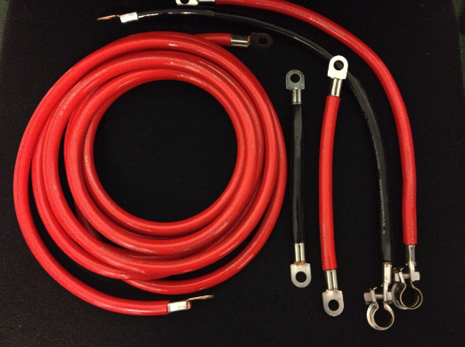
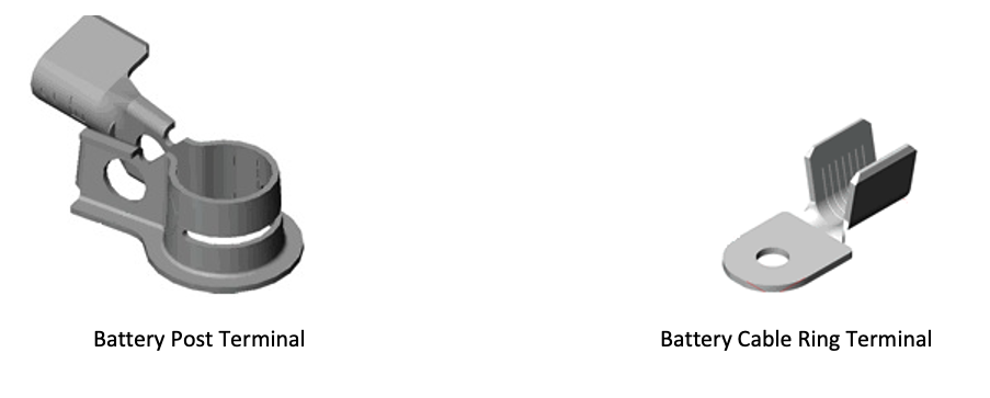
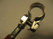
Major manufacturers of heavy duty terminals for automotive applications would market battery post terminals specifically designed to mate with the different geometries of the Positive and Negative battery posts. Terminals featuring engineered ribs or serrations that work within the connection to insure best possible unification. These terminals would be clearly stamped with the + and – symbols identifying them as positive or negative terminals. A large assortment of heavy duty ring terminals also made to SAE specifications in a diverse selection of hole sizes to accommodate customer requirements would be available. The terminals made for superior electrical for durability and corrosion resistance and are supplied on reels as continuous strip with the crimp ears up for automatic or manual termination.
5. Applicator Equipment
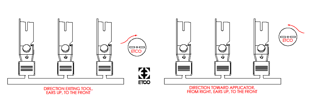
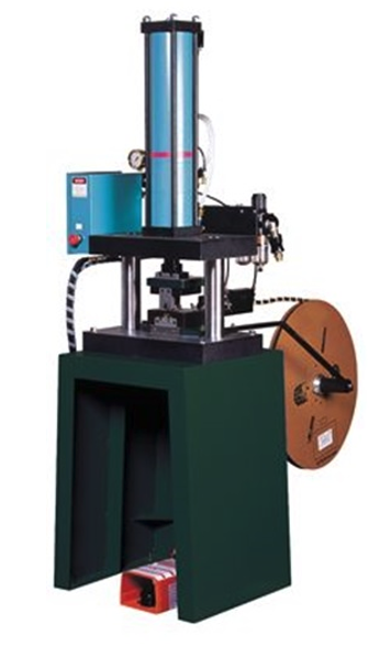
A trusted supplier’s applicator department should offer all the equipment needed to ensure an optimal terminal-to-wire crimp. Engineered tooling and applicators used in recommended presses offer best results. A variety of attaching equipment should be offered to accommodate the manufacturer’s range of terminals. Heavy-duty applicators used for heavy-duty terminals are designed for five-ton electric presses and 10 -15-ton heavy-duty air/hydraulic presses. The applicators should accommodate terminals for up to “00” gauge wire and offer detailed set-up and operating instructions. An applicator can be designed for semi-automated and fully automated crimping processes. Direction of feed and type of application should be clearly explained in accompanying collateral. Look for applicators that are designed to terminate more than one terminal.
Terminal Retention to Wire
The chart below offers retention values showing the minimum force required to separate the wire from the terminal’s wire crimp ear in both Newtons and lbs. /force. (Measurements taken without influence of an insulation ear) In some cases the manufacturer will recommend higher pullout forces to increase conductivity and specify crimp height to accomplish best all-around crimp performance.
| Size Of Conductor AWG |
Pullout Force mm2 |
Pounds | Newtons |
| 28 | 0.08 | 2 | 8.9 |
| 26 | 0.13 | 3 | 13.4 |
| 24 | 0.20 | 5 | 22.3 |
| 22 | 0.324 | 8 | 35.6 |
| 20 | 0.507 | 13 | 57.7 |
| 18 | 0.823 | 20 | 89.0 |
| 16 | 1.31 | 30 | 133.5 |
| 14 | 2.08 | 50 | 222.5 |
| 12 | 3.31 | 70 | 311.5 |
| 10 | 5.261 | 80 | 356.0 |
| 8 | 8.367 | 90 | 400.5 |
| 6 | 13.30 | 100 | 455.0 |
| 4 | 21.15 | 140 | 623.0 |