


Tensile Testing of Crimped Wire Terminals
for wiringharnessnews.com
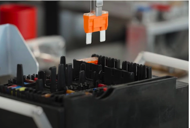
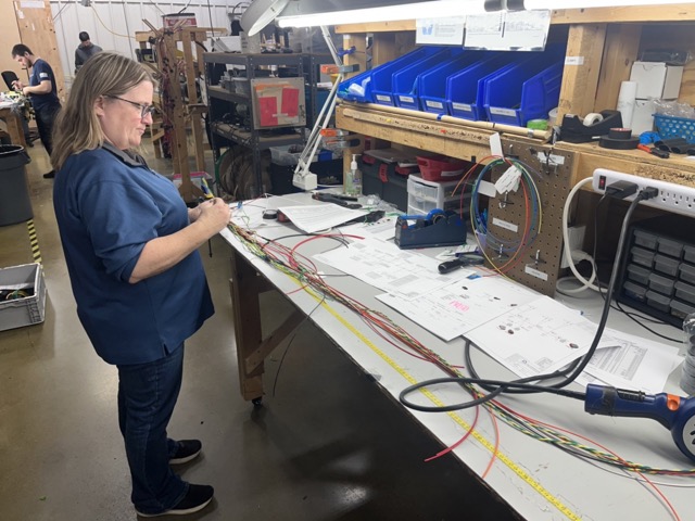
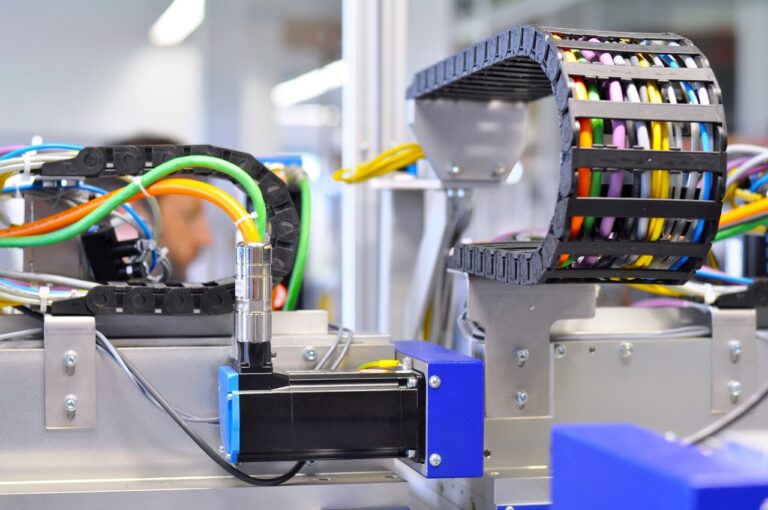
Wire harnesses and cable assemblies are used everywhere in connecting electrical and electronic equipment, from aerospace to domestic machines. While some are power conductors, many are signalling, connecting electronic controls and components. Predesigned for easy fitting, most are pre-bound and assembled with a variety of push-on connectors and may include permanent splices. This enables rapid assembly in mass production lines, and complete electrical pre-testing of all connectors.
Simple wire connectors, with terminals on both ends may be made semi-manually with bench presses, or fully automatically by machines that cut, strip, crimp and seal.
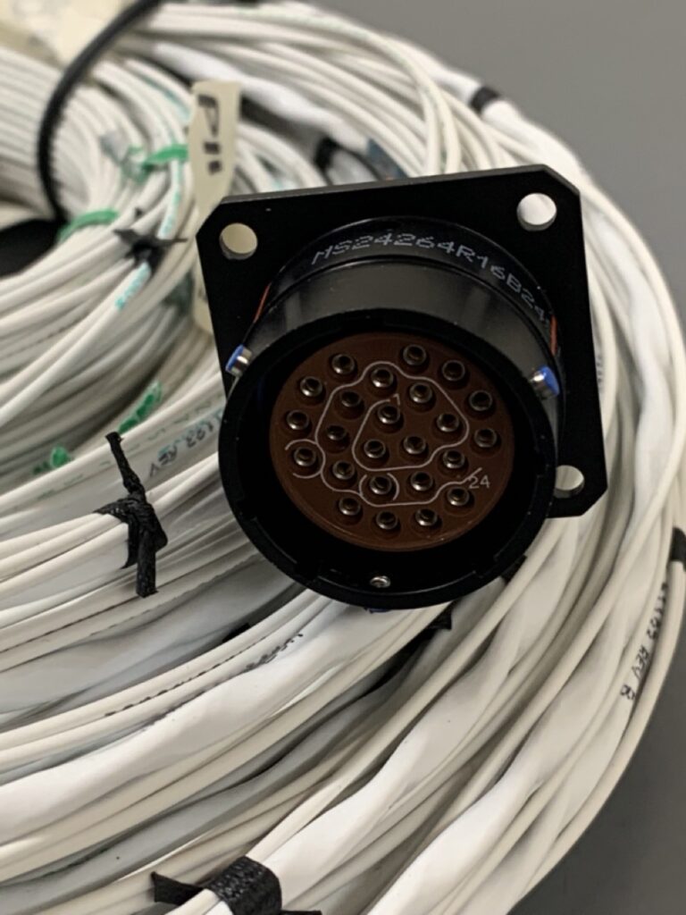
Most connectors are designed to be vibration-proof. Generally, they are not designed to sustain any weight, the conductor thickness being related not to strength but to electrical current capacity. Connectors may have ring terminals to screws with or without gripping profiles; they may be inline sockets and have clips for a positive fit security. They may be completely stable, or flexibly connect moving parts and control units. Maintenance must still be allowed, so disconnection must remain easy even after extended use, without risk to the crimped joint. In this context, crimped connections and terminals are almost universal.
Application
The crimping process is very precisely specified for strong, protected and durable termination of wires. While hand tools are used for small applications, powered bench crimpers with different forming dies are generally used—electric, hydraulic or pneumatic according to cable size. The principle is to apply sufficient gripping force around the exposed strands of a cable by compressing to a defined dimension, rather than by applying a specific force. The crimping tools are not calibrated as such but verified using gauge tools of calibrated pin size. Tools are dimensionally adjusted as required.
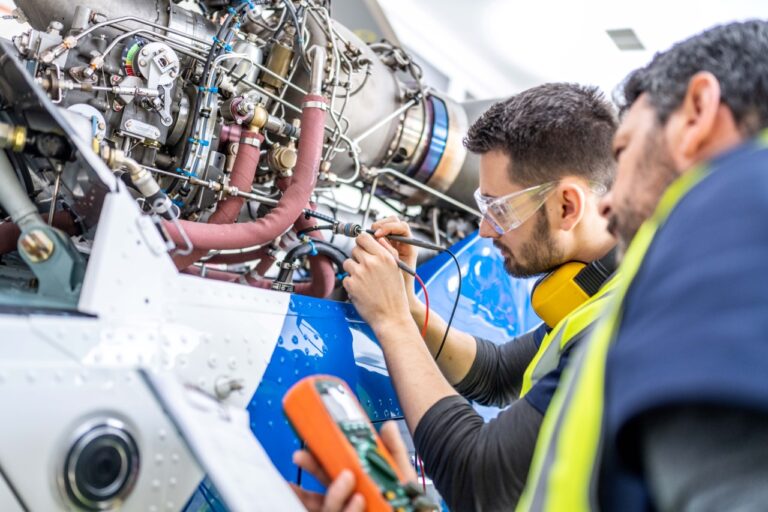
During termination, insulation is precisely stripped back, the strand ends inserted into crimp barrels to defined depth, and the crimping jaws effect the joint. Any risk of damage to strands is minimized in machine processes, but part of quality assurance is always visual testing and electrical testing. When specifying suitable connectors and terminals, other environmental tests may be applied, for example the effects of temperature or corrosion.
This is all good manufacturing practice and quality control, but the only way of really knowing the strength of a crimped terminal is to pull it. This can reveal production problems, where strand nicks, incorrect crimp height, or effects from changes in terminal supply, may not be clearly apparent. Assembling tensile test data in statistical process control (SPC) systems will also alert for tooling tolerance drift.
Testing
Several international and industry test standards specify test methods, with little variation in their parameters other than definitions of acceptable load bearing. Those in aerospace or military application are expected to be exceptionally robust. Originally, testing was done by hanging calibrated masses from wires that were gripped by their terminals, but this is slow, cumbersome, and less than precise. Instead, forces are applied by hand lever against a calibrated loadcell, or better, pulled at a known constant speed by motor control.
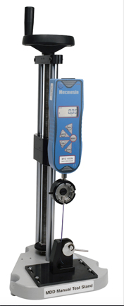
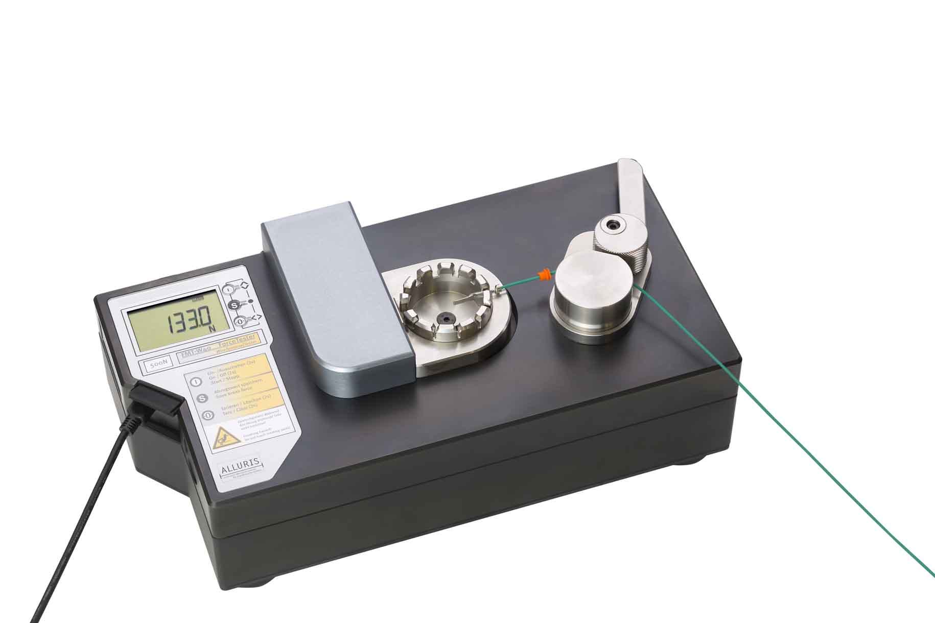
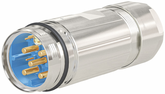
Machine selection is a matter of suitability for the forces required, the amount of testing being done, and location. Small, horizontal bench-mounted testers that can apply a force of around 1 kN (220 lbf), allow quality testers to insert single wires quickly, press a single button to activate the pull, and automatically record a peak or break force. Larger power connectors can require up to 5 kN (1124 lbf) applied force.
In design phases, it can be valuable to see not just at what force a crimped joint fails, but the way it fails. Strands can begin to break, a connector itself may deform and break, the whole conductor may break, or slip or pull-out of the crimped barrel may occur. Any elongation in the wire tail, however, must not be construed as slippage in the joint. These features can be identified on a full force-time trace using programmable tensile testers, as part of the development of jointing specifications.
Other features of testing can include changes in electrical conductivity or testing before and after environmental conditioning. Any of these tests may be accompanied by physical inspection, including sectioning and microscopic evaluation of the compacted strands for unevenness or voids.
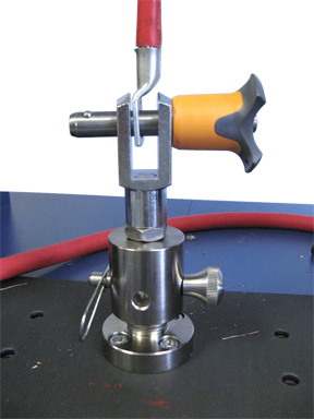
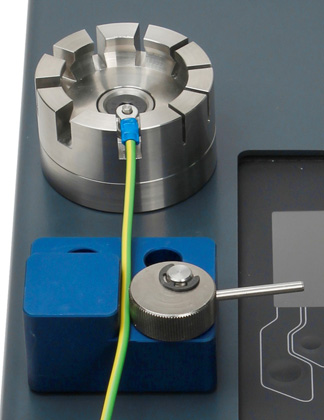
Gripping
The simplest assembled terminals comprise a single wire and a spade or ring connector, but there are many custom requirements, such as angled loops and lateral flags, where applying an axial pulling force to the conductor requires custom fixtures to grip the offset connector. Grips must be suitable for the terminal type, such that they hold without slipping and do not deform the terminal. Many can be held in a notch that allows a narrower wire through while pushing against the terminal barrel. Similarly, when gripping the tail of an insulated conductor, the grip must not bite and weaken the copper or aluminum conductors, but neither grip the insulation sleeve too loosely, such that it slips and extends.

Terminals themselves are often sleeved—for insulation (typically flexible), or to stabilize the entry of the conductor into the barrel (typically harder nylon, crimped on). In addition, the metal terminal may, for stability, incorporate insulation support. Do these features detract from the tensile test by hiding other weaknesses? Published test standards typically require their removal before pull-testing, but this can be difficult to do without damaging the conductor.
Standard methods
Standard methods are published to make testing consistent and repeatable anywhere, even with different test equipment. ASTM, BS, ISO, SAE, NASA and military standards bodies are among those with published methods. Typically, a constant speed of around 25 mm (1 in)/min is specified for a destructive pull-out test, though the US Underwriters Laboratories standard UL 486A assesses joint security by holding to one minute at a force prescribed for the wire gauge. Pull-out forces in these standards are comparable, except for military applications, which are more stringent.
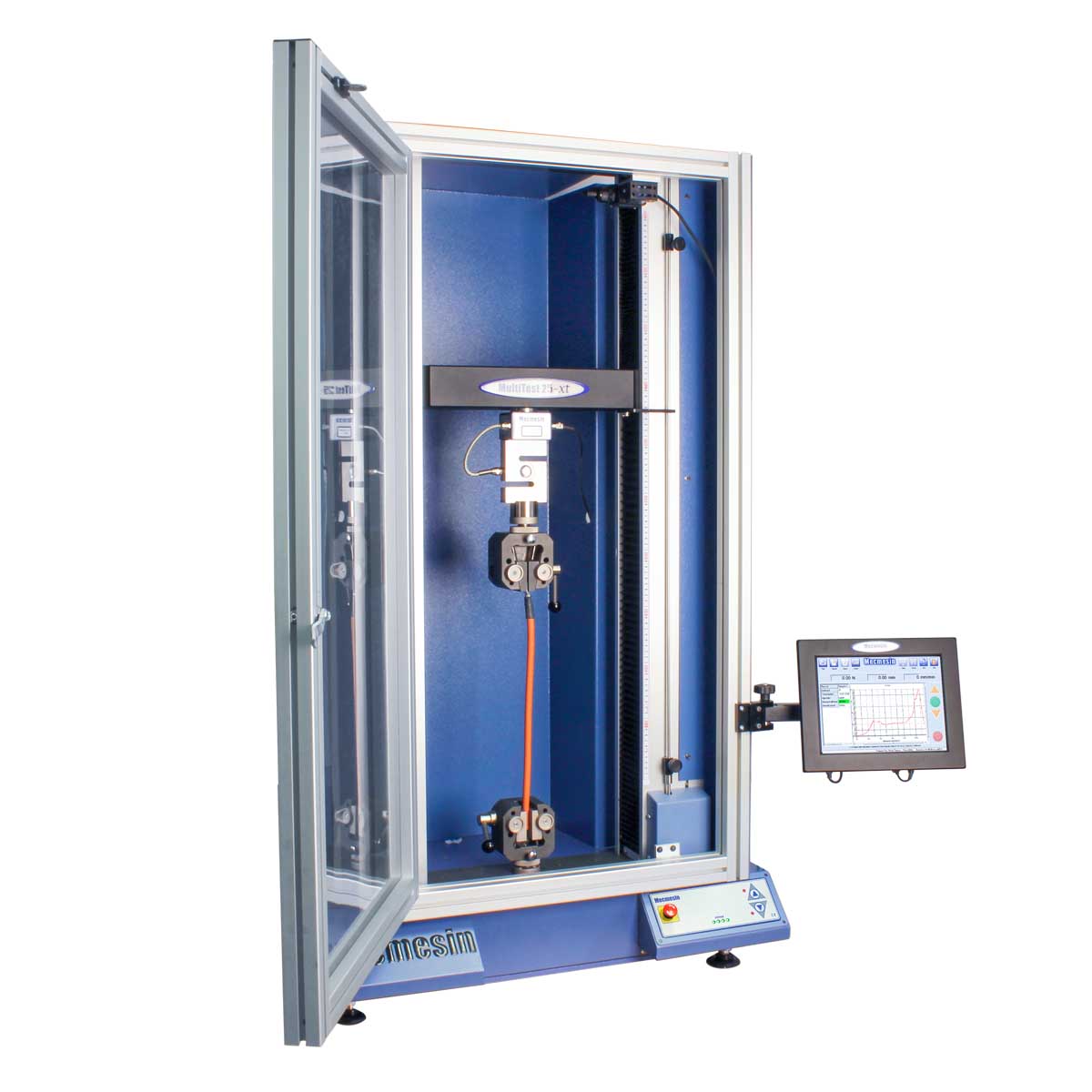
Universal tensile testers can also be used for connector insertion and withdrawal forces. With fixtures that precisely align male and female components, computer control can insert, withdraw, and cycle this action as required. Peak and average forces can be measured, and a load-time trace used to detect irregularities.
Custom fixtures on this universal tester guide push-on connectors to measure insertion and withdrawal forces.
Test standards references
ANSI/EIA 364-38B : Cable pull-out test procedure for electrical connectors
ASTM B913 -05 : Standard Test Method for Evaluation of Crimped Electrical Connections to 16-Gauge and Smaller Diameter Stranded and Solid Conductors
BS 5G 178-1 : Crimped joints for aircraft electrical cables and wires. Specification for design requirements (including tests) for components and tools
BS EN 2591 : Aerospace series – elements of electrical and optical connection, test methods
BS EN 61300-3-11 : Fibre optic interconnecting devices and passive components – basic test and measurement procedures Part 3.11: examinations and measurements – engagement and separation forces
BS EN 60352-2 : Solderless connections. Crimped connections. General requirements, test methods and practical guidance
DEF STAN 59-71 : Crimped electrical connectors for copper conductors
IEC 60512-13-1 : Connectors for electronic equipment – tests and measurements – Part 13-1: mechanical operation tests – test 13a: engaging and separating forces
MIL C-39029 /31B : Contacts, electrical connector, pin, crimp removable
NASA STD-8739.4 : Crimping, interconnecting cables, harnesses, and wiring
SAE USCAR21: Performance Specification for Cable-to-Terminal Electrical Crimps
SAE USCAR38: Performance Specification for Ultrasonically Welded Wire/Cable Termination
Author
Paul Montalto is a technical writer at Mecmesin, a Physical Properties Group company.