


By J. Ruben Lozano, VP of International Sales, Lakes Precision Inc.
The EV market is growing exponentially and is expected to grow approximately up to 27.5% by 2030. This new industry is slowly being introduced into the existing wire harness global manufacturing realm.
EV vehicle’s power train as well as their sophisticated electronics have introduced specialized wire requirements into the traditional wire harness mix alongside other traditionally processed wires and cables.
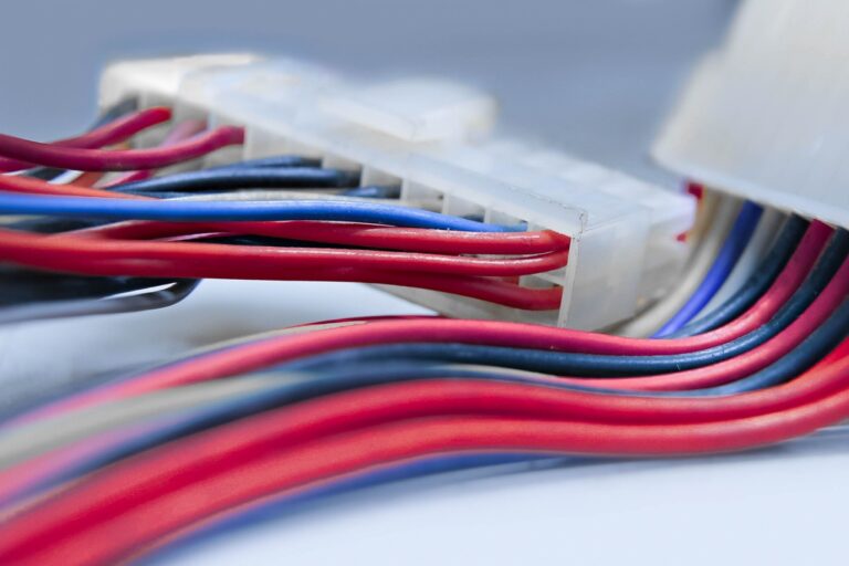
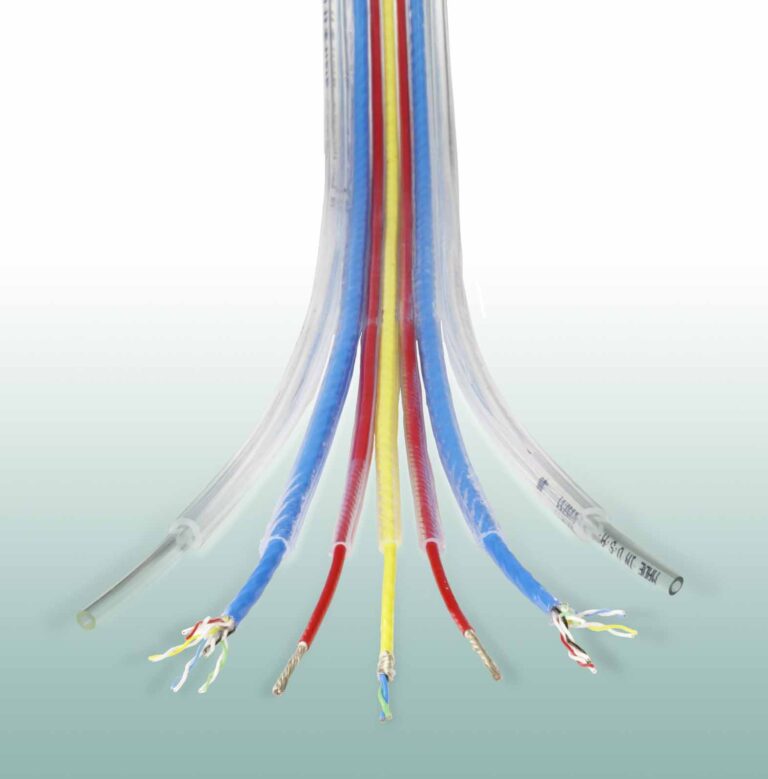
In this article I’m focusing on one kind of these new specialized types of wires, and how they impact traditional manufacturing methods. I call these wires “heavy layered cables” (or HLC for short). Figure 1 is a depiction of those wires, (the flattened layer graphic is for further illustration).
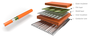
Figure 1. Heavy Layered Cables.
Because of the layered construction of these wires, a multi-function processing approach is needed. Our current manufacturing in-line processes are sufficiently capable to handle traditional fuel-based vehicle single-layered cables. But with the advent these heavy, multilayered cables in many instances, the in-line processing equipment capabilities have been overwhelmed. That’s because an in-line full process machine for HLCs requires all the necessary processing modules be contained within a common multi-process “toolbox” built around the physical perimeter of these wires. That can be an extreme challenge (Figure 2).
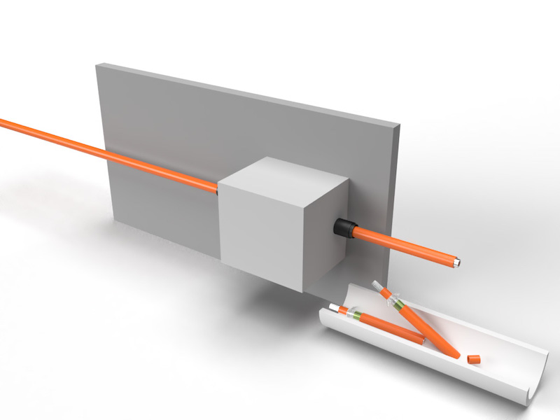
Figure 2. Inline processing of HLC wires.
Multi-function processing also means labor intensive manufacturing methods. However, labor intensive manufacturing approaches also includes challenges in coordination, precision, floor space, operator training and so forth. Because of this, new manufacturing equipment designs, and advances are being developed. These machines, in contrast to in-line processing, are based on the lateral processing method. This automatic processing system allows the equipment to have individual processing modules intended to work on each one of the layers of the HLC separately and individually. This reduces the complexity of designing a single multifunction processing module. (Figure 3).
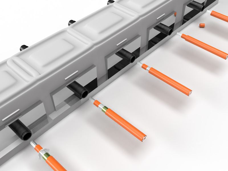
Figure 3. Lateral processing of HLC wires.
Manufacturing challenges.
By far one of the major challenges that EV wire manufacturers face is the exposure and/or removal of each single layer. Each layer presents differences in material and thickness; thus, the tool used to expose or remove these layers has to have the design capability of doing so. The tools currently being used are rotary slicing blades. Although there are many distinct OEM designs, we can classify them into three major types shown in Figure 4:
- Bayonet
- Tangent
- Peripheral
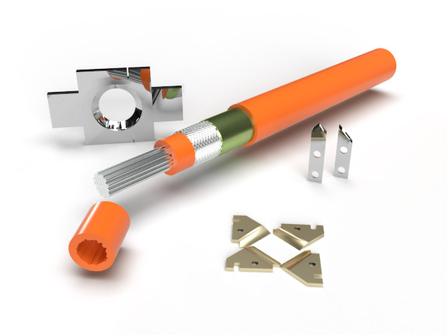
Figure 4. Clockwise from top left, peripheral, bayonet and tangent slicers.
Periphery slice cut and slug removal
Slice cut.
Bayonet and tangent slicing blades are designs used for rotary processing systems that allow penetration adjustability by programmable adjusting parameters on the equipment’s processing module. This achieves precise cuts on each one of the layers. On the other hand, the round geometry of peripheral slicing blades is sized for a specific layer, based on the layer’s cut perimeter. So, for each layer to remove or expose, you would need individually sized peripheral slicing blades.
Layer removal
Once you have cut into each layer, the next challenge is to remove the resulting slug. In order to do this, you either use the pushing method or the pulling method. The vast majority of the current stripping modules use the pushing method to do this. Which method to use strongly depends on the material’s property as well as the dimensionality of the material Itself. Materials such as films are exceedingly difficult to remove since they are extremely thin and neither a push nor pull approach works 100% of the time. Woven materials such as shields are also difficult to remove because of their loose construction and thinness. Shield layers are normally folded back to expose the subjacent insulation layer.
Insulation slug removal
Heavy layered cables for the EV powertrains require sufficient flexibility for efficient installation in the available space in the vehicle. Flexible insulation material has “rubbery” qualities. This translates into elasticity and compressibility characteristics. The combination of the elastic attributes of the insulation with the conductor core structure complicates the slug removal operation because there is synergy between them. The size of these wires requires hundreds of filaments to make the conductor core. As we all know, tightly twisted cores require more material per inch as compared to loosely twisted cores. For this reason, these wires contain “bunched” filament cores. Bunched cores are notoriously prone to uneven concentricity. They have peripheral filaments located either by themselves or in bunches away from the apparent core periphery. In order to avoid cutting or damaging these “satellite” filaments, the operator may sometimes limit the penetration parameter of the tangent rotary blades. This action creates a significant area around the core which is not physically separated from the insulation’s cross section. Even if allowing the operator to cut through the satellite strands, there still is an untouched cross section leftover around the remaining peripheral strands which is still attached to the rest of the insulation sleeve (Figure 5).
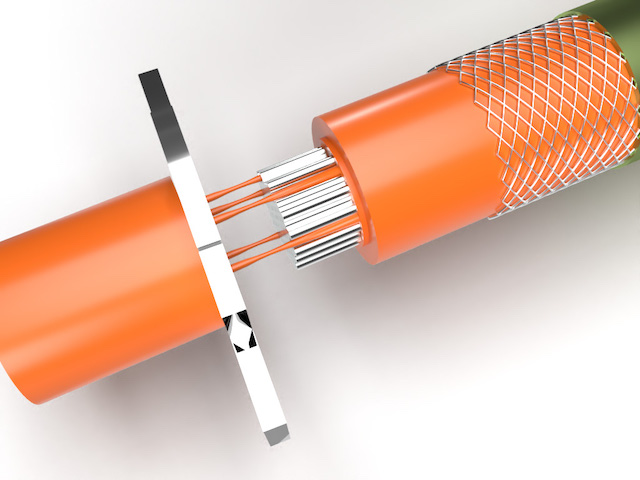
Figure 5. Closeup showing attached cross section insulation elastic strands being pulled in the stripping action.
Elastic attributes, mechanical
Some elastic materials are made out of randomly oriented cross-linked polymer chains such as the model depicted in Figure 6. The mechanical and thermal characteristics of these types of plastics inherently work against the slug removal process. In mechanical terms, pushing against the material compresses the polymer molecules. This action increases the wrapping force exerted on the underlying conductor core thus making it more difficult to cleanly dislodge the slug. Pulling against the material “unravels” the polymer molecules and extends the length of the material while reducing its cross section. When the elastic material gets close to its failure or rupture point, the polymer chains increase their resistance to the point that you need to exert added force to overcome the molecular resistance to split apart. The elongation limit of the material is dependent on its composition but an elongation of 115% (my own experimenting with a physical sample of an insulation section) at resting length is very possible.
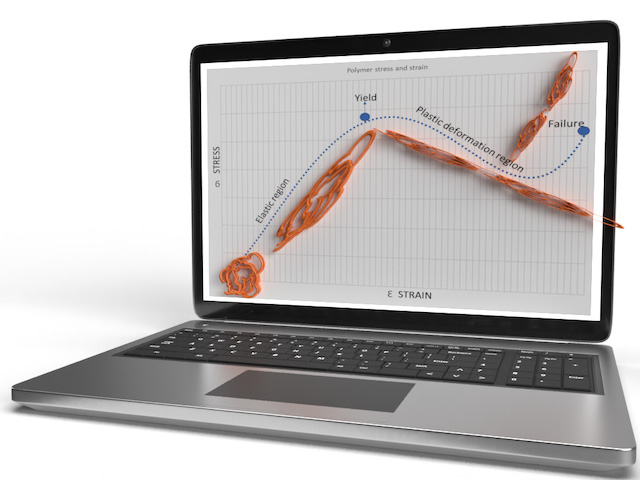
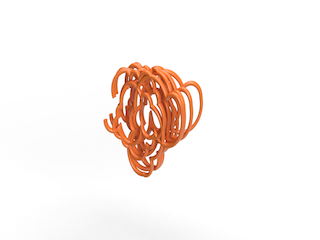
Figure 6. Model of cross-linked polymer chain molecules
Elastic attributes, thermal
Rubbery materials present a particular reaction to heat. Increases in temperature cause polymer molecules to compress and loss of heat loosens the molecular structure. I am not knowledgeable on the exact methodology used to manufacture these wires, but I would assume that considerable heat needs to be applied to the raw plastic material in order to make it fluid enough for the extrusion process. I would further assume that (because of the heat) the extrusion process deposits compressed polymer chains around the core periphery, forming the insulation cover. The resulting product is a wire which ultimately presents an insulation sleeve exerting some degree of compression force over the core’s peripheral area. This compression force thus plays a significant role in the difficulty dislodging the insulation slug, given the inherent coefficient of friction between the insulation material and the subjacent core metal. This would be especially apparent on longer slugs.
Sleeve compression factor of elastic material
So how would you measure or at least have an idea of how difficult it can be to dislodge an elastic insulation slug? One method I devised is to compare the circumference dimension between the mounted sleeve and the dislodged sleeve (Figure 7). The assumption would be that the mounted sleeve material is being stretched around the underlying core periphery. As such, it is under tension, but this tension force is not enough to break the polymer chains. When you remove the slug off the core (or underlying layer), the molecules relax and shrink the sleeve to their natural at-rest circumference length. Comparing the at-rest length to the mounted peripheral length, gives you a percentage factor which suggests how tightly the insulation is wrapping the underlying layer. I have tried this method with a few wire samples which I know were problematic to process. I found that this “compression factor” fluctuated between 6% to 14%. The common denominator between these samples was that they all had problems being dislodged by means of a rotary blade “pushing” them off. It was most problematic trying to dislodge them using bayonet or tangent type slicing blades. Peripheral slicing blades were more successful but would fail when there was variation of concentricity between different lots of the same wire being processed.
The formula for calculating this compression ratio (CR) is
![]()
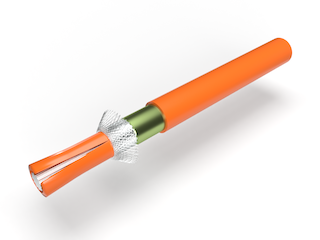
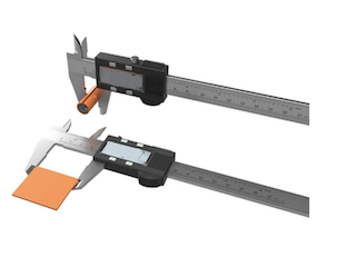
Figure 7. Calculating the compression ratio between stretched (mounted) insulation and removed and flattened insulation slug.
More successful and routine automatic processing of these types of wires is in the near future as improvements in the individual lateral process modules of modern equipment are implemented by the OEMS as a result of real time experience in the manufacturing floor. Meanwhile, the alternate solution is to apply manual labor or bench processes to these problematic issues.