


Are My Blades Sharp?
Understanding the physics of a wire processing blade cutting edge
By J. Ruben Lozano (B.I.E)
Materials, materials, we all are surrounded by them; myriads of materials, each one of them exhibiting unique and interesting physical, mechanical and energy characteristics. I am an engineer by schooling and experience – a manufacturing engineer at that. I have always been fascinated by the methods used to transform random material into something useful for our daily life. In our collective case, it’s the plastic insulation and copper into the circuitry that makes our cars, computers, appliances, etc. function day in and day out.
One of my favorite subjects in Engineering College was strength of materials. The theoretical part of it was so complex that it almost always managed to induce a headache on the younger version of me. In contrast, though, I thoroughly enjoyed the materials lab class. It was like a torture chamber for random test samples made from metals, plastics wood and other materials. Not that I enjoy torture. I just found great interest in understanding the theory behind the way materials bend, twist and break.
In this article, we’re going to scratch the surface, so to speak, on understanding the role of the cutting edge and sharpness of a wire processing blade.
After measuring a specific length of wire, there are three basic operations to perform to make it a connecting component in an electrical circuit. The first two operations, cutting to length and removal of an insulation slug (normally at both ends of the wire segment) are performed by either an individual function blade (cutting or stripping) or combined function blade (cutting andstripping). The third operation as we all know is the connector terminal crimping operation which involves other types of tooling and process.
Methods of cutting
Before we dive into the sharpness theme, we need to establish the different ways that a blade cuts material: Puncture mode, Tear mode and Slice mode.
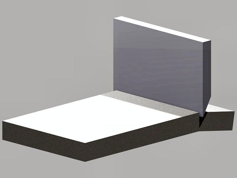
Figure 1. Puncture mode
In Puncture-mode (Fig. 1), the blade edge exerts a cutting pressure on a perpendicular vector to the material’s surface. Common uses for this are hacking, pick fracturing, punch holes, chopping, etc.
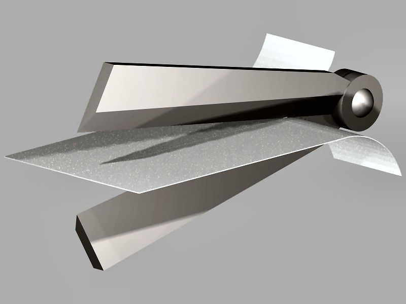
Figure 2. Tear mode
In Tearing-mode (Fig. 2), a pair of cutting edges mirroring each other on an angular position and pivoting around a common fulcrum exert simultaneous cutting pressures on opposed surfaces of the same material creating a shearing momentum. This is commonly used in cutting thin flat, flexible and semi-flexible sheet materials soft tissue surgeries, etc.
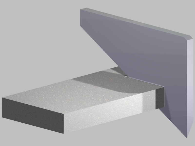
Figure 3. Slice mode
In Slice-mode (Fig. 3), a single cutting edge with an angled slope relative to the surface, induces a gradual cut across the material’s cross-section. Common uses are in surgery, slicing soft food material, or general soft and semi-soft flexible and voluminous material.
Brief description of the physics of cutting
In broad terms, the ability to cut a material can be defined by the Shear modulus:
S = F/A/∆x/h
S = Shear modulus
F = Force required
A= Cross section of material
∆x=linear deformation
h=length of the deformed cross section
Now, don’t worry so much about the formula above. It’s not my intention to induce a headache on you like the ones I got in College. It’s simply a way to understand a shorthand version of what’s needed to cut something. Translating the formula into plain English:
S= (Force required to cut through the material given the cross-section)
(How much does the material deform before failing)
The shear modulus is also known as the modulus of rigidity, and in essence is an indicator of how a given material resists deformation before fracturing or breaking. The higher the number, the more rigid it is. As an example, steel can have a modulus of 7 to 9, while rubber would have something close to 0.003, and PVC would be close to 0.11. A material with an infinitesimally small number would approach a fluid or a gas. So, that gives you a general idea.
Most thermoplastics used as insulations in our industry have enough rigidity which allows blade penetration and cutting of the material with relative ease. But keep an eye on the extremes such as a thermo-set plastic (too rigid) or rubber-like materials (too fluidic). Rigid materials require high pressure to be penetrated and fractured, while low rigidity materials require controlled slicing speed in order to avoid seizing the blade with too much induced friction.
Understanding the cut edge characteristics of a wire processing blade.
First, let’s take a look at stripping wire via the above three modes mode:
– The puncture-mode would not work very well, unless the wire was flat like a bus wire, or a flat grounding wire, or even a small-gauge multi-conductor parallel extruded wire.
– The tearing-mode would not very useful since the wires are not thin and flat like paper.
– Slice-mode, yes please, since most of the wires we process are round, semi-cylindrical and relatively voluminous.
The Slice-mode cut then explains the shape and geometry of the common blades we use in wire processing (Fig 4).
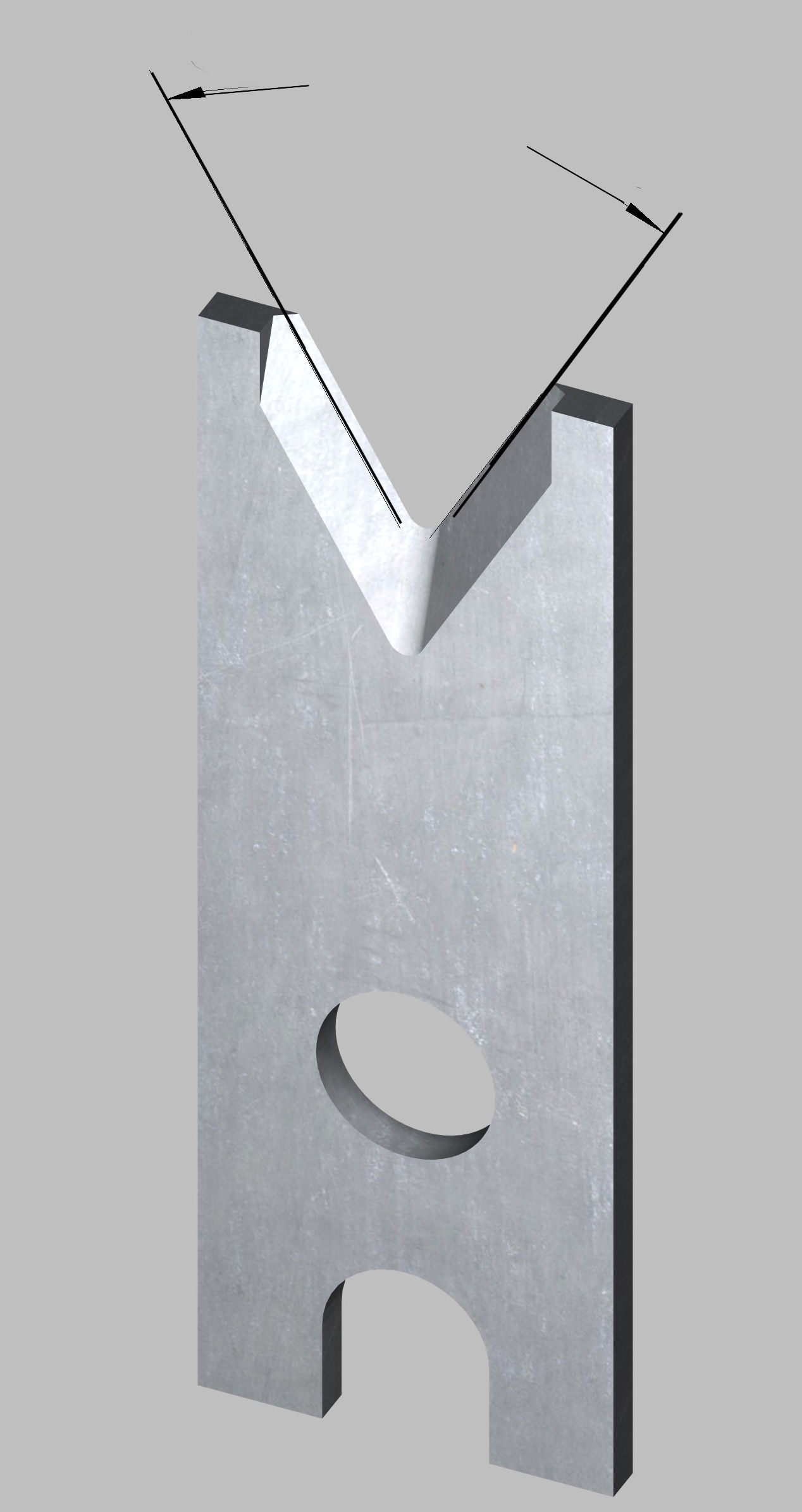
Figure 4. Slice angle
The cutting edges are slanted at standard angles forming a “V” shape opening with a radiused vertex at the bottom. The cutting portion of the blade edge is formed by a single wedge shape with a specific included angle (Fig. 5).
Figure 5. Cutting wedge
The reason for using a single wedge rather than a double wedge is because we are using the flat sliding surfaces as dimensional reference points for the strip dimension. The “V” angle opening between the edges is the “Slice” angle, while the wedge included angle is the penetration angle. The bottom radius of the “V” shaped edge of the blade is the conductor core enveloping edge. On that edge, the penetration angle is continued following the radius geometry (Fig. 6).
Figure 6. Bottom radiused wedge
Next, let’s look at the cutting mechanics:
The blades as we all know, are mounted opposite each other on a precisely calibrated blade holder located in the machine’s cutter-head section. The cutterhead is set in motion by a servomotor-driven assembly controlled by an on-board computer. As the blade edges close-in surrounding the wire’s insulation sleeve, a series of events ensue:
- Contact point with the insulation surface – a point on the blade’s sharp edge makes contact and deforms the material initiating a fracture at a high-pressure point resultant from the small contact area between metal and plastic (Fig. 7).
Figure 7. Contact point with insulation
- Slicing action begins – The blade’s angled edges transform the cutterhead down-stroke motion into a lateral slicing motion (Fig 8, Fig. 9). The friction generated by this motion, in combination with the wedge angle, propagates the crack or fracture on the material with a slicing speed.This is a function of the blade’s “Slice” angle combined the cutter-head downstroke speed. The slicing speed is a factor to consider, especially on very soft or rubbery insulations.

Figure 8. Slicing cut begins
Figure 9. Slicing cut view
- Bottom radius cut begins – The radiused wedge section penetrates the insulation (Fig 10, Fig. 11). But because of its relative position on the blade geometry, it’s not doing so in a slicing-mode, but rather in a puncture-mode, applying more deformation force to the plastic as compared to the lateral slicing sections of the cutting edge.
Figure 10. Bottom radius cut

Figure 11. Bottom radius cut view
- Full-penetration – Predetermined by the cutter-head’s on-board computer settings, the blades cut enough material around the conductor without going too deep as to contact the copper, aluminum or conductive carbon fiber filaments, (depending on the core’s material). This splits the insulation cross section into two areas called the free area and attached area (Fig 12, Fig. 13).

Figure 12. Full penetration cut
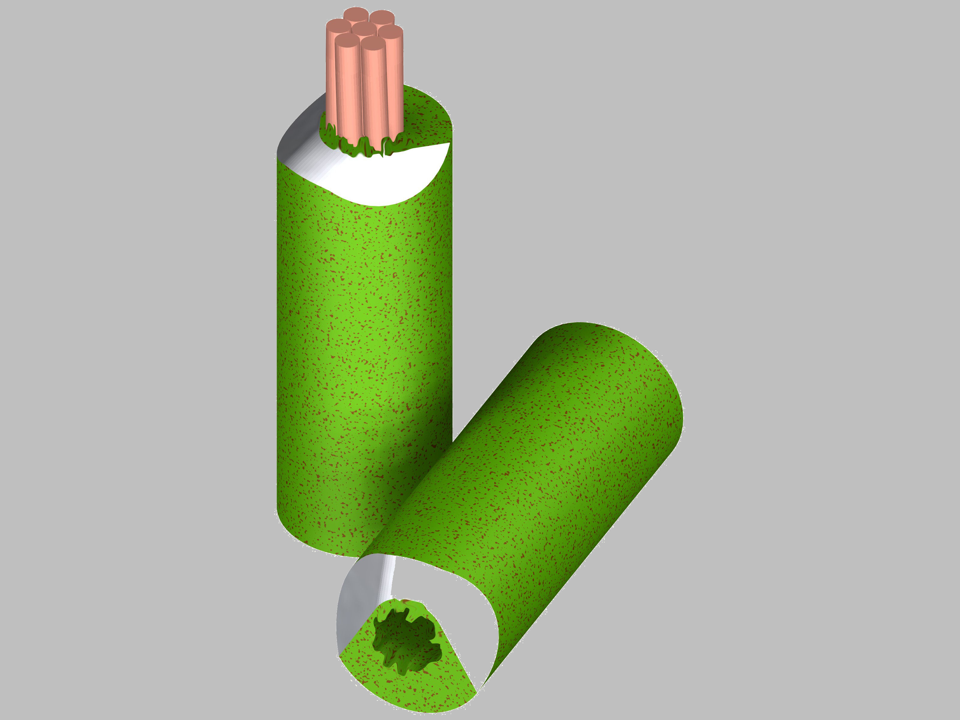
Figure 13. Strip showing torn attached are
- After the cut operation, the machine sequences the strip motion where the incoming and outgoing sections of the wire are pulled away from the blades to remove the insulation slug. During this operation, the attached area of the insulation cross-section is torn apart from the insulation sleeve, thus freeing the slug to be discarded. Typically, on a regular hexagonal laid conductor core with good concentric extrusion, the torn insulation area is about 16% of the total insulation sleeve cross-section (excluding the core’s cross-section). In other words, a 16% plastic donut is torn away while an 84% plastic donut is cut clean.
The effect of sharpness on the stripping process.
The generic concept of sharpness is very much related to a qualitative condition of a blade’s cutting edge. There have been numerous attempts to create an established parameter or scale to define the concept of blade sharpness. But they all revert to a generic point of comparison, like the sharpness of a surgeon’s scalpel, shaving blade, utility blade, kitchen knife, or something that is generically familiar to most of us. The surgeon scalpel is to most people the pinnacle of sharpness, but most knife hobbyists and enthusiasts would probably disagree. The truth is that any blade sharpness can be rated by its inherent intended use, and the methodology applied to achieve the sharpness factor. By the same token, the thickness of a blade does not necessarily imply sharpness, as sharpness is a dimensional condition related to the cross-section of the smallest end of a wedge. This can better be understood by the illustration below showing the relative sharpness on a 40 degree wedge, versus a 20 degree wedge. Even though the 20-degree wedge is thinner, its relative sharpness as compared to the thicker blade is duller.
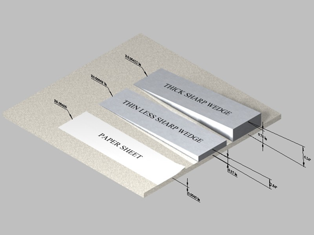
Figure 14. Cutting wedge thickness comparison
Figure 14 shows three cutting wedges showing that a thin wedge is not necessarily sharper than a thick wedge. The thin wedge (2.84 degree) has a sharpness radius of 0.000943” and a thickness of 0.35. The thick wedge (6.24 degree) is twice as thick at 0.78” but also twice as sharp with a smaller sharpness radius of 0.000422”. The third point of sharpness comparison would be a plain sheet of paper, no wedge, thickness of about 0.0040” and yet capable of slicing through skin, using friction alone.
A better functional criterion of a blade is the concept of relative blade sharpness vs. blade sharpness retention. This concept includes the fact that the sharpness of a blade deteriorates after every use, and thus the edge retention capacity of the blade is a function of wear. This wear factor has everything to do with the quality of the blade’s base material. In the case of wire processing blades, it’s the quality of the base steel, in combination with the quality of the manufacturing and sharpening methodology used by the manufacturer.
This also touches upon one of the most asked questions from wire processing blade users. How long will this blade last? What these users are really asking is what is the edge retention capability of this blade? And the answer should be considered in terms of the quantity of cycles. Specifically, the blade sharpness retention capability is a function of the material’s characteristics, defined by their physical properties (like the one defined earlier as the rigidity modulus and other related parameters). For example, a Surgeon scalpel inherently has a very short life span. Depending on the type of operation, he might go through several just for one surgery. Not only because of sterile considerations but also because the cutting edge is no longer precise enough for the procedure at hand. By the same token, a wire processing blade cutting an abrasive insulation material will not retain its sharp edge as long as the same blade cutting PVC or other softer, less abrasive material.
Linearity and non-linearity of material strain
Going back to the rigidity modulus, one of its components is the strain factor or the capacity to deform before failing. The softer or more fluidic the material is, the more non-linear its deformation response is. I guess this can be better explained by illustrating a common experience we all share. I bet you have experienced the occasion when you are wearing a jacket or sweater with a zipper opening. Under normal circumstances, you simply pull on the tab, and with slight resistance, and the zipper opens. On other, more frustrating occasions, the zipper slider body catches on a protruding section of clothing and latches on and for your dear life. Well, materials with a linear response to strain have molecular chains which react to the blade’s edge friction similar to a free-sliding zipper. They break apart and start a chain reaction on adjacent chains, thus collaborating with the cutting action. Other softer, more fluidic materials, have more dispersed molecular chains which get more and more tangled as the blade edge applies pressure and friction. The end result is that this entangling of molecular chains becomes rigid at the fracturing area and prevents or impedes the blade’s cutting effect. In this case, slicing speed control is much more effective than a sharper edge, because with slower slicing speeds, you allow the molecular chains to gradually break apart and give you a finer cut.
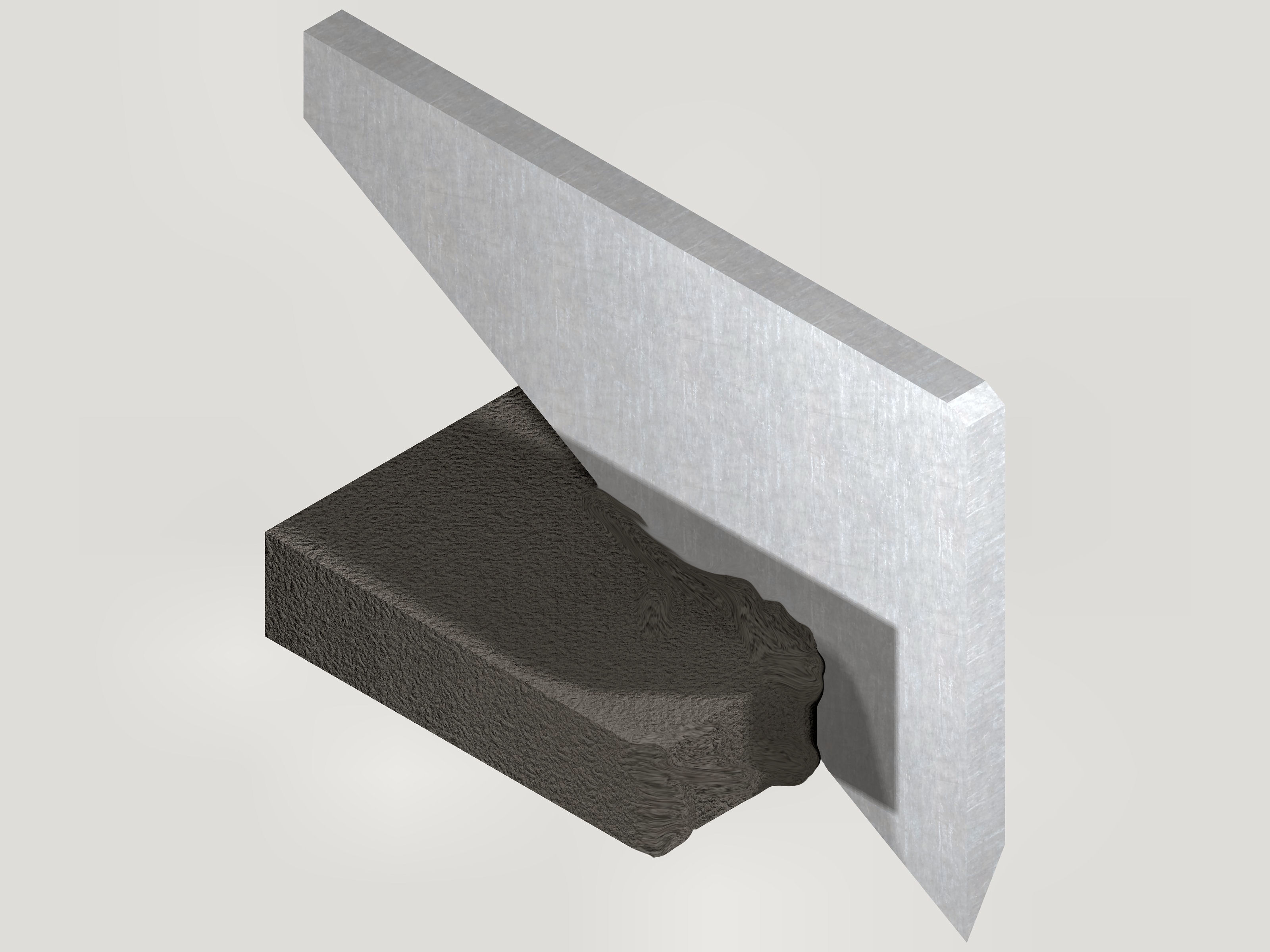
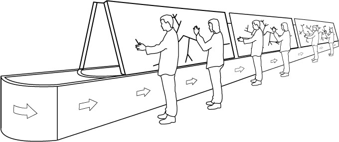
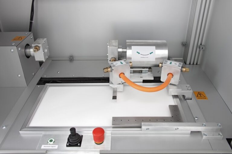
Example of a non-linear material such as rubber seizing onto a sliding shear at high speed.
And finally, let’s look at the relationship between the blade’s wedge included angle and its sharpness:
As we established prior, the blade’s included angle is not necessarily the blade sharpness. The real function of the wedge’s angle is to apply a splitting force which assists the sharp edge’s breaking apart the material’s molecular chains by friction. The larger the angle, the higher the splitting force applied by the wedge component of the blade. The wedge angle could be as reasonably wide, or as reasonably narrow as you might want to make it. Wire processing blades, like any other tool in our industry, are part of an economic whole, and as such, we could develop dozens of variations and configurations that would only increase the cost, without offering much in terms of process improvement.
Thus, the industry has pared-down the geometric styles to a few proven configurations. In the case of the wedge angles, the most common are 15, 20, 25 degrees, (favored by some Asian equipment designers) and 25, 30 and 40 degrees (favored by American and most European equipment designers). The most commonly used choice is 30-degree wedges. While the slicing angles are commonly 60 degree (30 degree slope each side) or 90 degree (45 degree slope each side) there are wider and narrower “V” or slicing opening angles, but those are for unique or custom processing.
In conclusion, we can surmise that the condition of sharpness is a very desirable trait on a blade, but it is but one of the many features and mechanical aspects contained in the cutting process. Sharpness is a fleeting thing, while its ability to deliver a quality process is a function of the blade’s edge retaining ability. This last feature is directly related to the steel material quality, manufacturing and the sharpening technology used by the blade manufacturer.
J. Ruben Lozano is the VP Sales and Marketing for Lakes Precision Inc.