


BACK TO BASICS
SOLDERED WIRE TERMINATION SERIES
By: Ray Cirimele, STI Electronics, Inc.
This is the first of a series that will review soldered wire terminations from beginning to end in detail. Wire preparation is the first step in the process and wire insulation removal (stripping) is the first step in wire preparation.
There are many methods of insulation removal. We will focus on manual insulation stripping using one of the two most common tools for manual stripping.
Thermal Stripper (Figure 1
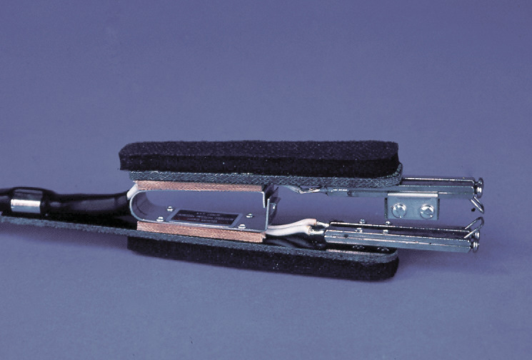
Figure 1. Thermal Stripper
Mechanical Stripper (Figure 2, to be covered in the next issue)
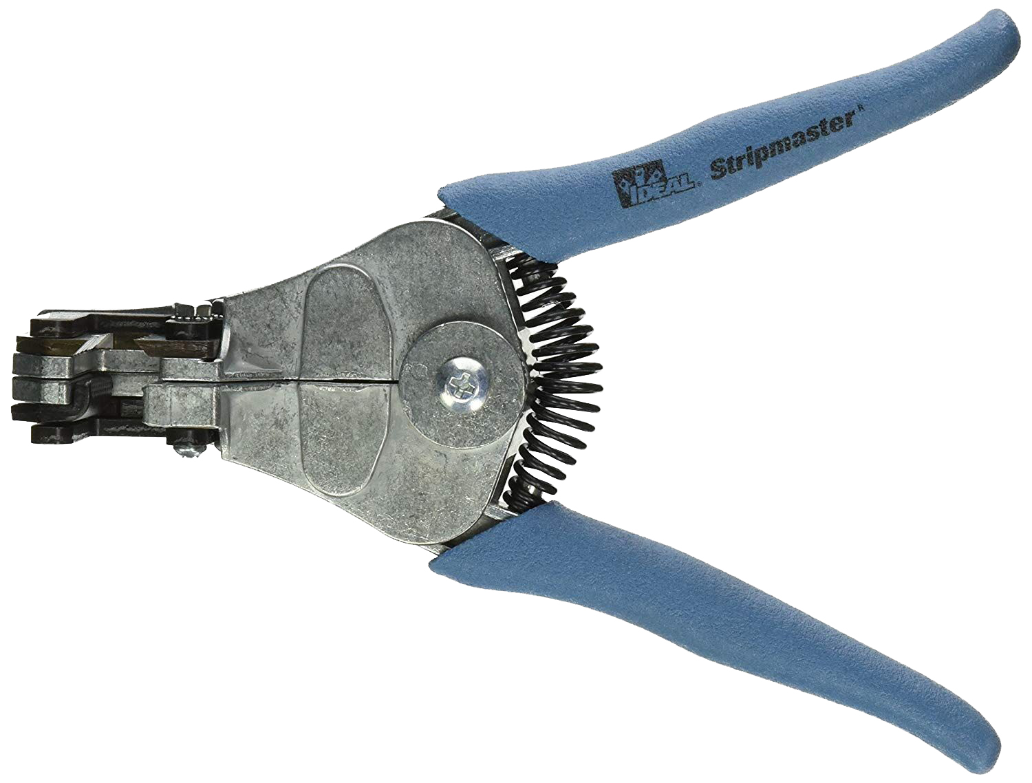
Figure 2. Mechanical Stripper
Thermal strippers usually come in a hot tweezer configuration with various styles of opposing elements (Figure 3). Thermal strippers have one major advantage over other types of handheld wire stripping devices. When the heated blades of the stripper come into contact with the wire insulation, it will slowly melt

Figure 3. Hot Tweezer Configurations
through the insulation, and with normal pressure applied, it will leave a very thin film of insulation between the blades and the wire strands. With no physical contact between the blades and the wire strands, strand damage from the stripping operation is avoided. This can be important because in the past, specification requirements specified that wire 22 AWG and smaller could not use mechanical strippers due to the slight risk that the cutting edges could scrape the strands exposing the underlying copper.
Step 1: Set the wire stop
Many of the handheld thermal strippers have adjustable wire stops to multiple wires have the same strip length (Figure 4). A setup wire may be used to ensure that the wire stop is set correctly before proceeding.
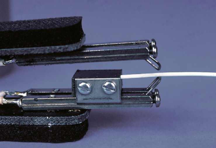
Figure 4. Set wire stop.
Step 2: Place the wire
Place the wire in the correct position between the blades (Figure 5).
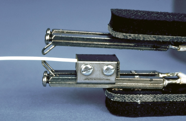
Figure 5. Position wire.
Step 3: Squeeze the handles
Use firm pressure to bring the opposing blades into contact with both sides of the wire insulation.
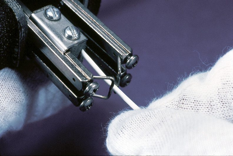
Figure 6. Firm insulation contact.
Step 4: Melt through the insulation
Allow the heated blades to melt through the insulation until resistance is felt from the wire strands (Figure 7). Give the blades a quarter turn before releasing the pressure and removing the wire. The quarter turn will ensure that there is no area of the insulation that did not make contact with the heated blades.
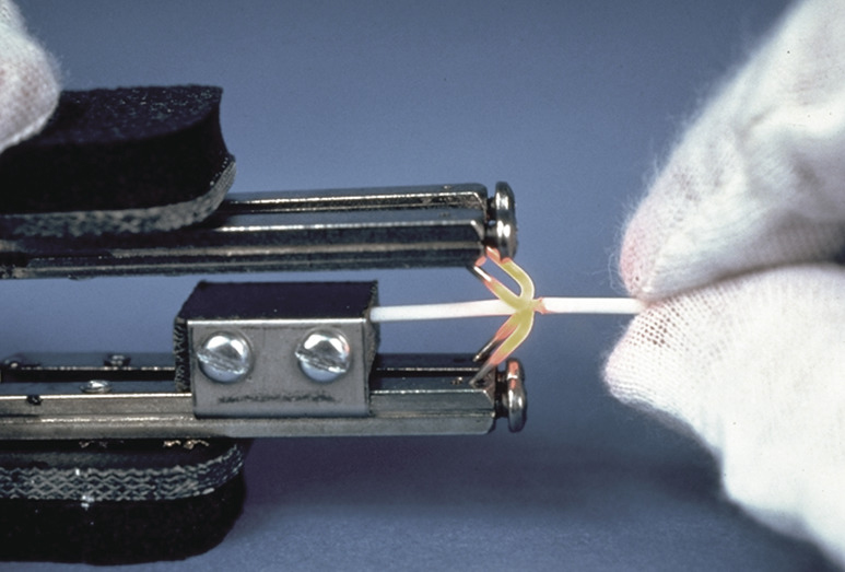
Figure 7. Melt through insulation.
Step 5: Removing the insulation slug
Give a gentle pull on both sides of the insulation to break the thin film of insulation still connecting the insulation slug from the insulation (Figure 8). When removing the insulation slug it is important to keep the pattern of the wire strands in the same condition as it was when covered with insulation.
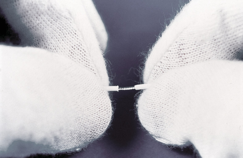
Figure 8. Gently pull insulation.
Importance of Wire Lay
Changes to the wire strand pattern can actually affect the electrical characteristics of the wire. The best way to maintain the natural lay of the strands is to slowly twist in the direction of the strand twist as you are pulling the insulation slug from the wire.
When the strands have been straightened out during the insulation removal, birdcaging of the wire strands is likely to occur (Figure 9) resulting in diminished long term reliability.
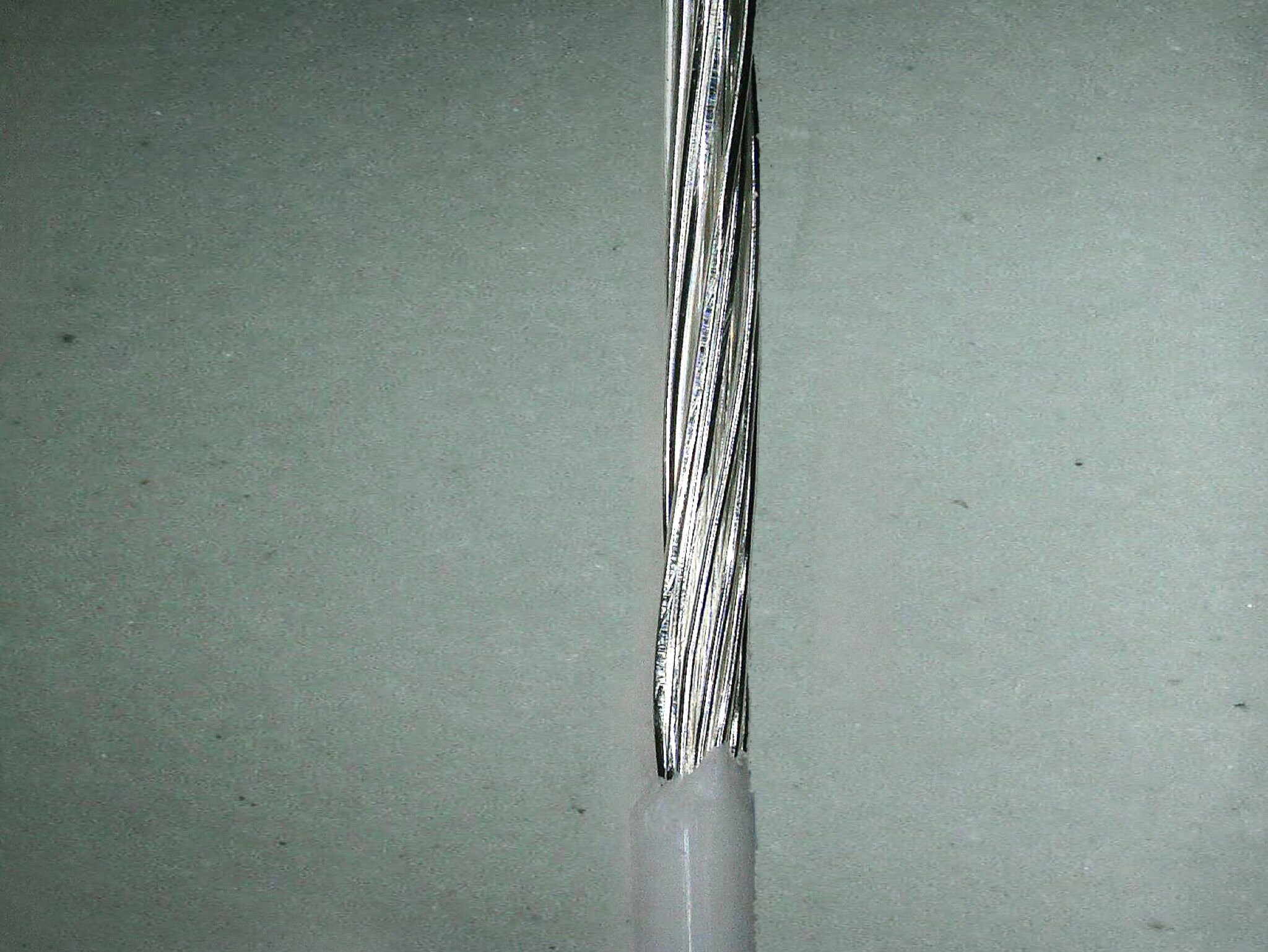
Figure 9. Birdcaging of straightened wire.
When the strands are overtwisted (Figure 10) it may result in diminished long term reliability and may also affect the electrical characteristics of the wire.
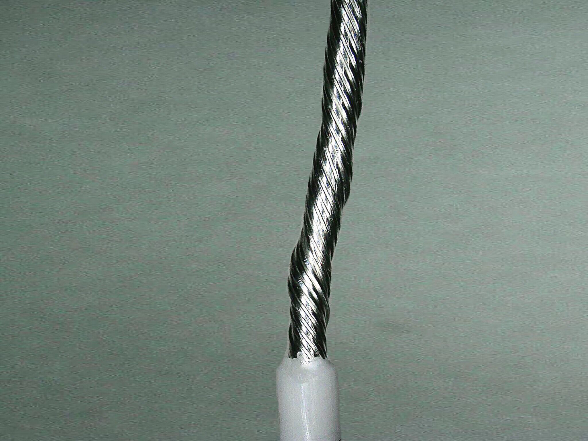
Figure 10. Overtwisted wire.
Obviously, leaving the strands in the same spiral lay they were in under the insulation is the desired condition because this will make it a lot easier for the electrons to navigate through the strands to his destination.

Figure 11. Perfect wire lay.