


Improving Practices:
A Candid Conversation with Randy Cherry – IPC

If your’ve ever attended the EWPT Expo or any WHMA Conferences, you likely ran into the smiling face of Randy Cherry, Director of Validation Services at IPC. Randy has made a career of working with companies in the electronics industry. His knowledge of the harness industry is vast, and he has a near photographic grasp of the WHMA/IPC A-620 specification. I make it a point to have at least one conversation with Randy at every trade event, as I always learn something.
As things open up, Randy is resuming his audit schedule. I thought it would be a good idea to touch base with him to see what he is noticing in the field. Overall, he thinks the industry is doing a very good job at adhering to quality standards set forth by IPC/WHMA A-620. But he does see some concerning patterns and areas for improvement. Following are some of his observations.
Automated Equipment
During my visits to cable and wire harness companies, I notice some really good practices, but also some not-so-good. I do notice manufacturers tend to hang on to legacy equipment a little too long. They try to make these older machines perform year after year. At some point, they start having some quality issues. They’re just not getting the clean cuts or the good of crimps they did when the equipment was newer, for example.
Another thing I notice at the wire harness companies I visit; is they typically fall behind on preventive maintenance (PM) for their assembly equipment. I do not need to overstate how important PM is to the manufacturing process. Downtime cannot be tolerated because a key piece of equipment is unable to perform to peak efficiency. A solid PM program or schedule should automatically alert the maintenance technician so that nothing is missed. They will get much more consistent results over the life of the equipment this way.
Hand Crimpers
I notice particular neglect when it comes to hand crimpers. With older hand crimpers, verification of a solid crimp sometimes gets overlooked. When a company is assembling a very complex harness that requires several unique hand crimpers, this verification becomes especially difficult; but it really needs to happen. Companies should follow the guidelines in section 19 [A-620] and use wires and terminals to make some sample crimps. They should perform a pull test and/or dimensional testing on samples from each hand crimper and track the results (Statistical Process Control). If a hand crimper fails to meet the test requirements for a certain crimp and wire gauge it should be replaced or repaired.
Many of the hand crimpers I’m seeing are not designed for continuous use in an industrial setting. They were purchased at the local hardware or department store. These hand crimpers were not designed to provide a consistent crimp per IPC standards. IPC/WHMA-A-620D for Class 3 requires that all crimp tools, including hand crimpers, control the crimping operation to the extent that once the crimping operation has begun, the tool cannot be opened until the cycle is complete. In other-words, a full-cycle/ratcheting tool is required for Class 3 crimping.
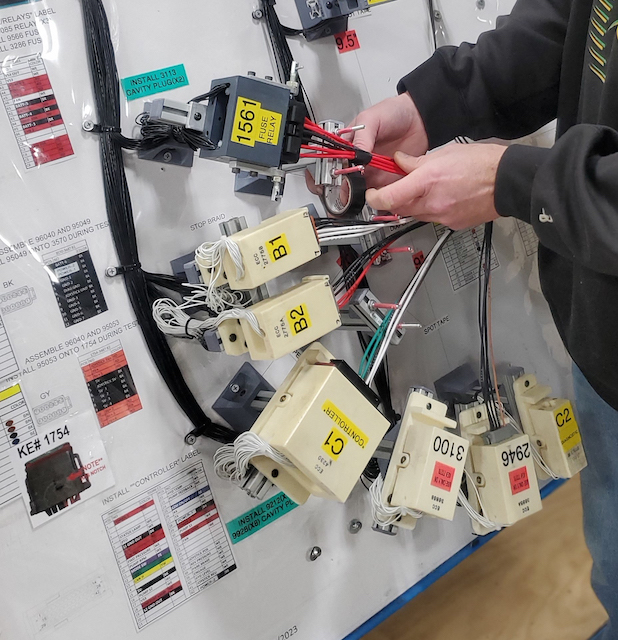
It is a good idea to list all the hand crimpers and machine crimping tools on the Production Traveler/Work Order or a Work Instruction. Too often I see operators using the wrong hand crimper or do not have the crimping machine set-up properly to produce an acceptable crimp to the customer’s drawing. Having a pictorial document or spreadsheet showing the crimp height information for the family of terminals being used saves time during new job setup.
Soldering:
Another area of concern involves using different solder alloys for wire tinning and soldering wires to printed circuit boards. I never saw this issue until the industry moved from tin/lead solders, to lead-free. For example, I have seen operators tinning wire with a SAC 305 lead-free solder alloy, and then try to solder the wire to a printed circuit board with a 63/37 tin/lead alloy. Since the melting temperatures of each solder alloy combination are different, you will never achieve a good intermetallic bond. Plus, you’ve now contaminated the SAC 305 alloy with lead. It’s a good idea to review how you tin your stranded wires and how you plan to attach them to the printed circuit board.
A big concern I have is with operators mixing solder fluxes. It is a bad idea! The fluxes need to be compatible. You need to use the same external flux for tinning wires that will be in the flux cored solders for attaching the wires to the printed circuit board.
Cleaning is another area that does not seem to get much attention when tinning or soldering wires. Flux has a tendency to wick up under the wire insulation when processing steps are not followed, or if proper cleaning is overlooked. Trapped flux residue under the wire insulation will result in corrosion of the wire over time. IPC/WHMA-A-620D calls for the use of low activity fluxes (L0 and L1) for tinning and soldering. Many companies have started using no-clean fluxes and solders which may not need to be cleaned. Regardless of which flux or flux cored solders you select, always review the manufacturers requirements for cleaning. The goal is to have either a clean tinned wire or, if any flux reside is left behind, it is benign.
I have one more observation on the wire tinning process. Folks should always remember to have the solder tinning pot added to the preventive maintenance schedule for replacement and replenishment. Typically, these solder pots are very small and only hold a few pounds of solder. It is not cost effective to analyze the solder if the amount is small. Replacing and replenishing on a regular basis ensures your solder alloy stays below the maximum limits for solder bath contamination (IPC/WHMA-A-620D Section 4.1.1.1.1 Table 4-1). It’s a good idea to track the daily, or weekly usage of the solder tinning pot to determine the frequency for replacement and replenishment. You may need to have a few solder samples analyzed to establish a benchmark of data to determine how often this should be done. The used solder alloy material can be scraped and reclaimed by an authorized vendor to get back some of the value.
Training:
Other challenges that I see involve an overall lack of training due to high employee turnover and a limited talent pool of candidates. IPC now offers Wire Harness Assembly for Operators training. This on-line or instructor lead course provides an overview of useful information and tips for cable and wire harness operators. This training course is targeted for operators who are new or need a refresher to the cable and wire harness assembly methods. (See full article on WHO on page xx).
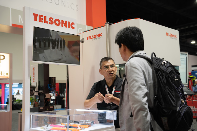
Ultrasonic Welding for Splices
During my travels, I get to see many innovative solutions in the cable and wire harness industry. The increased use of ultrasonic welding for splicing is one example. It is especially useful if you are splicing two different materials. An example would be welding copper and aluminum stranded wires together. This wire combination appears most often in automotive applications. Remember you need to keep the equipment very clean and well-maintained to ensure ultra-sonic weld integrity.
Final Inspection:
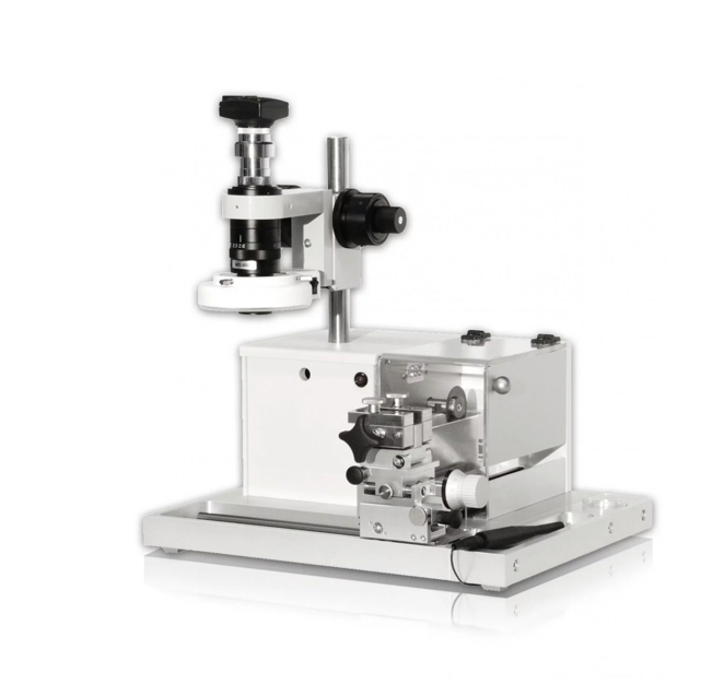
One big area for debate I find in the cable and harness industry is with final harness assembly. Inspectors, operators and engineers often differ on what is acceptable, and what is not. I’m noticing that harnesses are inspected at too high of a magnification, revealing “issues” are not really defects or even bad process indicators. IPC/WHMA-A-620D has two tables (Table 1-1 and 1-2) that show the correct magnification level based on wire gauge. Typical inspection magnification range is 1.5X to 10X. The maximum referee magnification inspection range is 1.75X to 20X. You only need to use the referee magnification inspection range to verify a harness that has been rejected at the inspection magnification range. You never need to go above 20X magnification for production harnesses, unless you are troubleshooting a particular manufacturing problem.
Use of IPC/WHMA-A-620D/Third Party Verification
Many companies that I visit are still learning and understanding the benefits of using IPC/WHMA standards. The IPC/WHMA-A-620D standard contains valuable information covering materials, methods, tests and acceptability criteria for producing crimped, mechanically secured, or soldered interconnections associated with cable and wire harness assemblies. Companies who support this standard find comfort in knowing that their manufacturing processes meet or exceed this standard.
Third party verification is another method of knowing that your manufacturing processes are compliant to this standard. IPC Validation Services is one option to accomplish this strategy. Companies that meet or exceed the IPC/WHMA-A-620D standard have set themselves apart from others in the industry. This is a key marketing advantage over the competition.
About IPC
IPC is the global association that helps OEMs, EMS, PCB manufacturers, cable and wiring harness manufacturers and electronics industry suppliers build electronics better. IPC members strengthen their bottom line and build more reliable, high-quality products through proven standards, certification, education & training, thought leadership, advocacy, innovative solutions, and industry intelligence.