


Creative Use of Existing Instrumentation to Meet Exacting Requirement
A Two-Part Article: PART I
By Christopher E. Strangio, CAMI Research
Overview
Measurement of insulation resistance (IR) occurs by applying a voltage between two conductors and observing how much current flows through the insulation. Dividing the applied voltage by the flowing current using Ohm’s law produces a value of insulation resistance.
Typical PVC or Teflon electrical insulation work extremely well, and as a result, only a miniscule current can be detected, so little, in fact, that we refer to the current as “leakage current” and need to raise the voltage to hundreds or thousands of volts to achieve detectible current flow. This, in fact, motivated the development of high voltage testers many years ago.
Recently, testing cables and connectors at high voltages poses some new challenges. Advances in electronic packaging often involve fitting complex circuitry into ever-smaller spaces, particularly in airborne or spaceborne applications. Consequently, the interconnects between increasingly compact electronic modules must shrink as well. NanoD connectors have typical contact spacing of 0.025” (0.635mm), half the spacing of microD connectors which themselves reflect a similar reduction in contact spacing from the generation before microDs appeared on the market.
As connector design forces pins into smaller spaces, pin spacing shrinks, and high voltage testing for proper electrical isolation between pins pushes the applied test voltage down to avoid air breakdown. Requirements presented by our customers over the last few years now require an IR of 10 GΩ at 100 Vdc, and this, in turn, demands a current measurement sensitivity of 10 nA or better.
Here we describe how we combined two existing test instruments to achieve the exacting measurement, and (in Part II) the results and precautions.
The Method
My company’s CableEye® HVX-21 multi-channel high voltage cable test system offers a leakage current sensitivity limit of 200 nA which we can reduce to 100 nA for special applications using a sample-averaging method we developed. However, we still remain unable to reach the 10 nA sensitivity required for new applications.
Rather than re-engineer the programmable high voltage power supply in our tester to meet the new requirement, we use an existing source measure unit (SMU) — a single-channel high-voltage test instrument, Keithley 2400-series SourceMeter™ SMU, which has the needed sensitivity, and provides a remote-control capability allowing us to integrate it with our existing control software. The successful result met our objective quickly and efficiently and offers increased-sensitivity IR measurements at a much lower test voltage than had previously been possible.
Under normal operation, our HVX tester serves as a data-acquisition peripheral to a standard Microsoft Windows™ PC running our test software which issues control commands to the tester and reads responses from it as the measurements are completed. Test results appear on a video monitor for immediate review and diagnostics, and these results may be printed, if desired, to fully document the test. Referring to Figure 1, the tester receives commands through a USB channel to first perform a low-voltage continuity and resistance test on the attached wiring, also referred to as Unit Under Test (UUT).
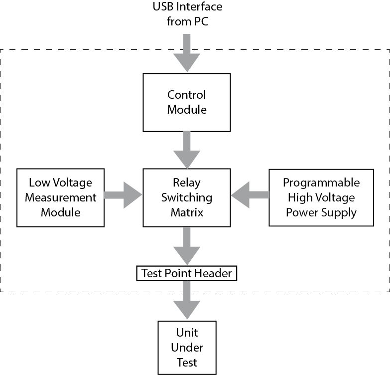
Figure 1
If the wiring matches the model cable and the connection resistances comply with the set limit, we disengage the low voltage module seen in the diagram through the relay matrix and drive a high voltage signal onto a distribution bus. Relays switch the high voltage stimulus signal onto the test points to which the UUT is attached. The system then sequentially applies high voltage to individual wires in the cable through the relay matrix while collecting leakage results from each wire tested.
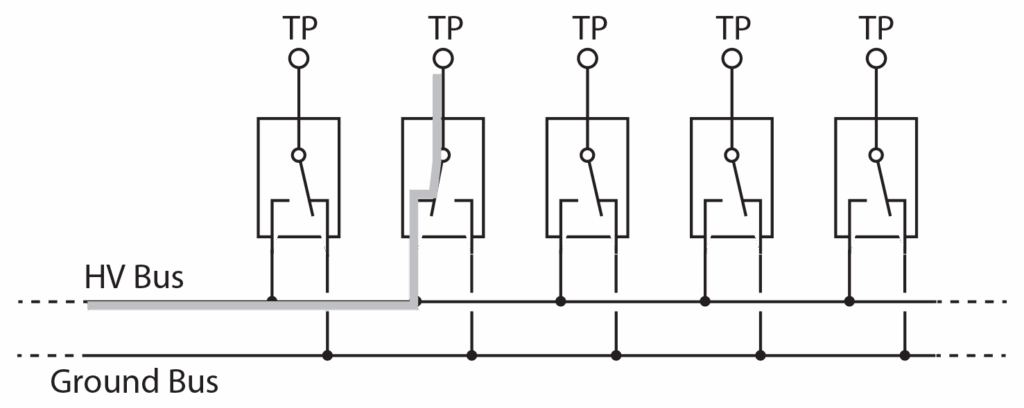
Figure 2 illustrates a high voltage distribution bus and five typical relays. When a relay is energized, it connects the bus to a test point that drives a signal into the UUT. For a two-ended connection, two relays energize, one at each end of the wire. All relays that are not part of this connection remain de-energized and connected to the return path (ground bus). The electric field between the wire receiving the high voltage and all other points in the wiring presently at 0 V provides the opportunity for current to flow through any vulnerable areas in the insulation. Ideally, no current flow will be detectable.

Figure 2
Figure 3 shows how an external instrument, in this case the SMU, replaces our internal high voltage generator. The SMU provides a high voltage stimulus needed to force current through insulation in the wire and has enough sensitivity to make the nanoampere current measurements we need.
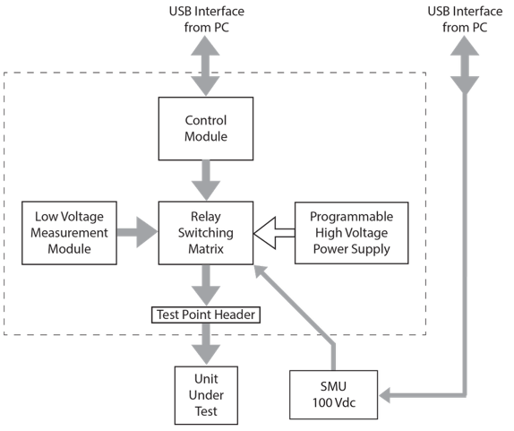
Figure 3
The system basically works the same way by first making a low voltage continuity test to confirm that the UUT is wired correctly and has acceptable connection resistance limits. It then engages the external SMU to apply 100 Vdc to the wiring network and measures the leakage from each wire. A second USB channel controlling the meter issues commands to ramp the voltage up, holds it for the specified dwell time, and returns a current leakage measurement to our PC control software.
We describe our results and precautions in Part II.
© 2024 by CAMI Research Inc. All Rights Reserved
CableEye® and the CableEye Logo are Registered Trademarks of CAMI Research Inc.
Achieving 10 GΩ IR Measurements at 100 Vdc
Creative Use of Existing Instrumentation to Meet Exacting Requirement
A Two-Part Article: PART II
In Part I (last issue) we looked at the reasons behind specifying a 10 GΩ IR measurement at 100 Vdc, and a creative approach of using existing instrumentation to achieve it. Here, we review the results and precautions to be taken.
Results
Figure 4 shows the on-screen test result from a special test board designed to demonstrate the measurement function. On this board, individual wires joining pairs of test points represent typical wires in a cable, and 1% precision high voltage resistors connect one end of each wire to ground. The precision resistors represent leakage. Each measurement completes in about five seconds.

Figure 4
Although we use resistors here to represent leakage, in a realistic application where we check the performance of wire insulation, we would typically set a tolerance limit of, for example, 10% to ensure that the insulation resistance does not fall below 10 GΩ less 10% (9 GΩ). In practice, wire insulation will exhibit much higher resistance than the lower limit we set, so failing a test like this would generally indicate a serious problem like the presence of moisture, clearance problems between pins, contamination present between pins or wires, or thinned or otherwise compromised insulation.
Precautions
When testing for leakage above 1 GΩ, the relative humidity could add parasitic leakage to the measurement. We suggest employing a temperature/humidity sensor when making high-resistance leakage tests to document ambient conditions on the test report along with insulation resistance values. We recommend connecting an environmental sensor to a USB port to report real-time, continuous measurements of temperature and humidity alongside the IR data.
While the relay matrix itself, as well as the internal wiring, and lead wires connecting the meter to the CableEye tester, could contribute parasitic leakage to the measurement, careful testing in our test lab with no UUT attached provided assurance that such leakage as may exist comes in at the level of background noise and has no effect on the intended UUT measurement.
During the test, the UUT itself should be placed on an insulated surface and situated away from the presence of external electromagnetic interference (EMI). Because of the miniscule currents we measure during this test and the fact that a cable, particularly a long one, may act as an antenna, be aware of the potential for induced noise from switching power supplies, electric motors, nearby radio transmitters, and overhead lighting. Testing shielded cables provides some protection against the effect of external EMI.
A test operator carelessly handling connectors on the UUT affords another potential risk. Contamination from oils on the skin or substances in the environment creates an opportunity for parasitic leakage between connector pins. Given the miniature size of connectors subject to a 10 GΩ test, the risk becomes low, but not zero.
Summary
Combining the best qualities of two different off-the-shelf instruments to measure extremely low leakage currents in multiconductor cables provides test capability that would be otherwise very difficult to achieve. Doing so also requires awareness of environmental conditions that, for less stringent measurements, would have no adverse effects on the test results, but for highly sensitive tests as described here, could cause artificially low IR results leading to rejection of an otherwise passing assembly.
CAMI Research produces highly versatile Cable & Harness Test Systems for countless applications in Transportation, Energy, Medical Devices, Defense, Scientific R&D, Telecom, and more. Used for assembly, prototyping, production, and QC of standard or custom cables, CableEye® testers accurately display and document electrical properties such as continuity, resistance, dielectric breakdown, insulation resistance, miswires, twist pair relationships, and intermittent faults. camiresearch.com